Table of Contents
Advertisement
Quick Links
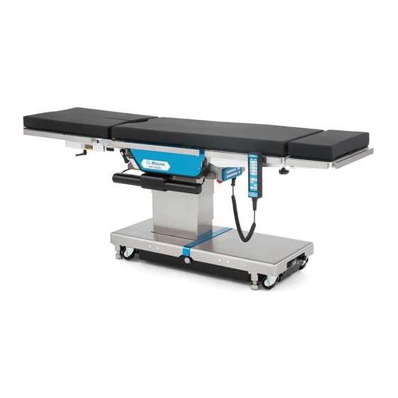
Operating Table MOT-VS600
Operator's Manual
The operating table is designed to support a patient during surgical procedures.
Using it for other purposes may result in damage or injury.
The operator and the person in charge of the maintenance of this operating table
MUST read this Operating Table Operator's Manual carefully and understand the
contents before operating, inspecting, adjusting, or servicing the table.
Keep this Manual where it is readily accessible for reference by those concerned
in case of need.
MES-CK18-600-20EN Ver.8 2021-07-05
Advertisement
Table of Contents

Related Manuals for Mizuho MOT-VS600


Summary of Contents for Mizuho MOT-VS600
- Page 1 Operating Table MOT-VS600 Operator’s Manual The operating table is designed to support a patient during surgical procedures. Using it for other purposes may result in damage or injury. The operator and the person in charge of the maintenance of this operating table MUST read this Operating Table Operator’s Manual carefully and understand the...
-
Page 3: Table Of Contents
Contents Introduction 1. Introduction ............1 Before use 2. Before use ............... 7 Component identification 3. Component identification ........15 Operation 4. Operation .............. 21 Maintenance and inspection Installation and battery charging ..........22 Specifications Switch On/Off power ..............31 In the case of emergency ............33 Troubleshooting Lock and unlock the operating table ........34 Before contacting... -
Page 5: Introduction
Introduction 1. Introduction... - Page 6 Introduction...
- Page 7 Introduction Introduction This Manual is intended to support safe and effective operation of the operating table. Read this Manual carefully and familiarize yourself thoroughly with its contents (operation, inspection, adjustment, servicing) before operating the table. Using the table without following the instructions contained in this Manual may cause a serious accident.
- Page 8 Accessories Introduction „ Standard compornents and accessories Mattresses (for head, back, seat and leg) Control unit Main unit Power cord Operator's manual...
- Page 9 KIDNEY UP KIDNEY DOWN FLEX REFLEX BRAKE UNLOCK LEVEL ENERGIZE ON/OFF PRESS TO LOCK BRAKES z Mizuho Original Pad for Head Section for Back Section for Seat Section for Double Leg Section Type A Type A Type A Type A for Seat Section...
- Page 10 Introduction...
-
Page 11: Before Use
Before use 2. Before use... - Page 12 Please read carefully before use Misuse of the operating table could cause damage, electric shock or fire. Before use Any serious incident that has occurred in relation to the device should be reported to the manufacturer and the competent authority in which the user and / or patient is established. Head plate or leg plate WARNING CAUTION...
- Page 13 Patient's position during surgical operation Before use WARNING - Make sure to attach the provided mattress securely. Improper attachment may cause a patient to get injured. - Position a patient's body at least 10 mm (0.39 in) away from the side rails. When using the electric scalpel, they may become hot and if the body touches the rails, it may cause the patient to get burned.
- Page 14 Others CAUTION Before use When used together with other medical equipment or accessories - Before using another devices or accessories, read carefully the instruction manual of the device and make sure that the operating table will not be affected adversely. Before fitting an accessory of third party company, make sure to contact your distributor or us.
- Page 15 Warning label: details and position Warning label is attached on the following area of the operating table. Before use Before using it, make sure to check the contents of the warning label. „ WARNING, CAUTION labels (8) (10) (1) C655740 ...
- Page 16 „ Other labels (1/2) Before use (17) (11) (12) (14) (16) (18) (16) (15) (13) (11) (22) (19) (20) (21) (22) (12) C655725 (13) C655726 (11) C655758 C655759 C655762 C655763 C655760 C655761 (14) C655722 (15) C655721 (16) C655724...
- Page 17 „ Other labels (2/2) Before use (24) (24) (24) (24) (24) (29) (32) (31) (30) (24) C653620 (25) C655736 (26) C655737 (27) C655755 or C655750 or C655751 or C655756 (28) C655734 or C655746 ...
- Page 18 „ Symbol mark for labeling Before use Symbol Description Label no. Indicates a possibility of injury or even death if operates the (1) (2) (3) (4) (6) (7) table without following the warning. (8) (10) General prohibition sign General mandatory action sign. Emergency stop Refer to the operators manual (5) (9)
-
Page 19: Component Identification
Component identification 3. Component identification... - Page 20 Main unit Auxiliary switch Component identification Slide cylinder Control unit connector Emergency stop switch Back plate attaching/ Lift-up unit(*3) removing levers Seat plate Leg plate(*2) Back plate(*2) Head plate(*2) Leg plate swinging handle Leg plate fixing lever Leg plate flexing lever Control unit Head plate flexing lever Head plate...
- Page 21 Control unit Component MOT-VS600DK identification Power lamp Pilot lamp Battery lamp REV. TREND. TREND. Reverse Trendelenburg: Trendelenburg: Head down Head up TILT LEFT TILT RIGHT Lateral tilt: Left down Lateral tilt: Right down BACK UP BACK DOWN Back plate bending:Up Back plate bending:Down TABLE UP TABLE DOWN...
- Page 22 Cordless control unit (optional) Component identification MOT-VS600DK Pilot lamp REV. TREND. TREND. Trendelenburg: Head down Reverse Trendelenburg: Head up TILT LEFT TILT RIGHT Lateral tilt: Right down Lateral tilt: Left down BACK UP BACK DOWN Back plate bending:Down Back plate bending:Up TABLE UP TABLE DOWN Table up...
- Page 23 Foot switch (optional) „ Common to MOT-VS600 Component identification Elevation: Elevation: Trendelenburg: Reverse Lateral tilt: Lateral tilt: Down Head down Trendelenburg: Left Right Head up...
- Page 24 Component identification...
-
Page 25: Operation
Operation 4. Operation LOCK RELEASE Installation Lock and unlock and battery Switch On/Off In the case of the operating Brake Lateral tilt P36 charging power emergency table Release Tilt the Change height of Slide the Change height of Trendelenburg the tabletop Flexing the lift-up unit back plate... -
Page 26: Installation And Battery Charging
Installation and battery charging „ Preparation CAUTION Operation 1. Move the operating table to a flat area. Equipotential grounding 2. Check the battery lamp. - Ground the equipotential terminal and a medical If the battery lamp (orange) on the control unit grounding terminals by means flashes, battery charging is required. - Page 27 Installation and battery charging „ Installation space Operation This product requires the installation space shown as below. 2.5 m (98.43 in) or more 2.5 m (98.43 in) 2.5 m (98.43 in) or more or more 2.5 m (98.43 in) or more...
- Page 28 - Make sure to use the dedicated power cord with "MIZUHO" logo. - Make sure that the connector of the power source is not intruded in by fluid and is not...
- Page 29 Installation and battery charging NOTE - Useful life for the battery used Operation for the operating table is about 2 years. Once it reaches the useful life, ask your distributor or us for battery changing. - Battery life will vary greatly depending on the operating conditions.
- Page 30 Installation and battery charging „ Attach the control unit Operation 1. Insert the connector into the receptacle by aligning it properly with the guide. Insert „ Detach the control unit 1. Turn the ring of the connector in the direction of the arrow until it stops.
- Page 31 Installation and battery charging „ Self-diagnosis function Operation The operating table has a built-in self-diagnosis function to check if the operating table and control unit work properly. 1. Connect the power cord. 2. Press on the control unit. 3. Press and one of the function switches on the control unit at the same time.
- Page 32 Installation and battery charging „ Cordless control unit (optional) CAUTION Operation Preparation - Do not mix old and new batteries, and different battery 1. Use a slotted screwdriver to remove the battery brands. cover of the cordless control unit. - Do not apply an impact to the cordless control unit or get 2.
- Page 33 Installation and battery charging „ Cordless control unit (optional) Operation Setting up When using the cordless control unit, set up the cordless control unit and the rotary switch on the operating table. If there is anything you don't understand about setting it up, contact your distributor or us.
- Page 34 Installation and battery charging „ Cordless control unit (optional) 2. Setting up the operating table Operation The rotary switch is inside the base of the operating table. 1. Remove the cover of the base. 2. Set the rotary switch to the number (0, 1 or 2) you set up to be operated by remote control.
-
Page 35: Switch On/Off Power
Switch On/Off power „ When using power of NOTE medical grade wall outlet Operation - If an emergency occurs Power on or the power is turned off completely, unplug the power 1. Turn on the power switch on the base. cord from the medical grade The power switch (green) and the battery wall outlet. - Page 36 Switch On/Off power „ When using battery power NOTE Power on Operation - When using the battery power, the power will go off 1. When the power cord is not connected to the automatically if no commands power connector and the power switch on the are given for 15 minutes or base is turned off, press on the control unit.
-
Page 37: In The Case Of Emergency
In the case of emergency In an emergency, you can stop operating table from WARNING moving by pressing the emergency stop switch. Operation The emergency stop switch „ Operating in an emergency must be used only in an emergency. 1. Press the emergency stop switch. The buzzer sounds and the operating table stops. -
Page 38: Lock And Unlock The Operating Table
Lock and unlock the operating table LOCK „ Lock operating table WARNING Operation 1. Press simultaneously. - Make sure the table is locked The brake will actuate and the operating table after the brake is applied. will be locked and the power lamp on the base - Do not unlock the brake with the patient on the table. -
Page 39: Brake Release
Brake Release RELEASE „ Release the brake with the CAUTION emergency brake release handle Operation After turning the emergency In case of electrical trouble, operating table can be brake release handle in the moved by using the emergency brake release handle. UNLOCK direction, be sure to return it in the LOCK direction. -
Page 40: Lateral Tilt
Lateral tilt „ Left down WARNING Operation 1. Press simultaneously. Make sure the patient on the The tabletop will move to the left down position table is secured when tilting the table. Otherwise the patient as viewed from the head end. may fall off the table. - Page 41 Lateral tilt NOTE Operation RESTRICTION - When the height from the floor to the table top is in the range of 720 mm (28.35 in) to 620 mm (24.41 in), the maximum angle of the left down position is 15° and that of the right down position is 30°.
-
Page 42: Trendelenburg
Trendelenburg „ Reverse Trendelenburg WARNING (Head up) Operation Make sure the patient on the table is secured with Mizuho 1. Press simultaneously. operating table accessory The tabletop will move to the head up position. fixtures when heading up or down the table. Otherwise the patient may fall off the table. - Page 43 Trendelenburg NOTE - The maximum angle of head Operation up or head down is as follows from the level position. 30° 40° 40° 30° - When the tabletop in a Trendelenburg / Reverse Trendelenburg position is tilted to the opposite side, it will stop in the level position.
-
Page 44: Tilt The Back Plate
Tilt the back plate „ Move up the back plate WARNING Operation 1. Press simultaneously. Keep your hands away from The back plate will move up. the gaps during the operation of the table. Otherwise you may get injured. MOT-VS600DK 90°... -
Page 45: Change Height Of The Tabletop
Change height of the tabletop „ Move up the tabletop CAUTION Operation 1. Press simultaneously. Do not lower the table with the leg The tabletop will move up. plates folded at 90°. The tips of the leg plates may come in contact with the base and get damaged. -
Page 46: Slide The Tabletop
Slide the tabletop „ Move in the Foot direction NOTE - Maximum sliding from the Operation 1. Press simultaneously. center position of the tabletop The tabletop will be slid in the foot direction. is as follows. Foot direction 415mm MOT-VS600DK (16.34 in) 415mm Head direction 250mm... - Page 47 Slide the tabletop NOTE - If the back plate is lower than Operation the level position, the tabletop can not be slid to the leg side from the standard center position and the buzzer will sound. When moving up the back plate higher than the level position, the tabletop can be slid to the foot direction.
-
Page 48: Flexing
Flexing „ Flex (center up) WARNING Operation 1. Press simultaneously. Keep your hands away from Both the back plate and the seat plate will be the gaps during the operation of the table. flexed down. Otherwise you may get injured. Back between plate... - Page 49 Flexing NOTE - In the position where the Operation tabletop center point is in the leg position beyond the standard center position, flexing (center up) will not operate and the buzzer will sound. If the tabletop center is slid to the head side beyond the standard center position, flexing (center up) will operate.
-
Page 50: Change Height Of The Lift-Up Unit
Change height of the lift-up unit (MOT-VS600DK/MOT-VS600DHK only) „ Move up the lift-up unit NOTE - The highest moving-up Operation 1. Press simultaneously. position is 150mm (5.91in) The lift-up unit will move up. from the surface of the tabletop. Move up - The lowest moving-down MOT-VS600DK 150mm... -
Page 51: Return To Level
Return to level „ Return the tabletop to the NOTE level position Elevation, sliding, and braking Operation do not function. 1. Press simultaneously. The tabletop in a position of Trendelenburg, lateral tilt, back plate flexing, or lift up will return to the level position. -
Page 52: Adjustment Of Head Plate
Adjustment of head plate WARNING to 4 different positions upward (max. 60°) and to 6 different positions downward (max. 90°). The head Operation - Be sure to tighten the head plate can also be detached. If the head plate moves, the Flexing patient may get injured. - Page 53 Adjustment of head plate „ Attachment WARNING Operation 1. Hold the both sides of the head plate and align the - Be sure to tighten the head inserting shaft of the head plate with the receiving plate fixing handles securely. If the head plate moves, the hole in the back plate or the leg plates, and insert.
-
Page 54: Adjustment Of Back Plate
Adjustment of back plate The back plate is detachable. WARNING „ Detachment Operation - The back plate weighs 10kg (22lbs). 1. Pull up the both the back plate attaching/removing Pay special attention when lever placed on the bottom of the back plate at the handling it. - Page 55 Adjustment of back plate Attachment WARNING Operation 1. Make sure both of the back plate installation pins - Make sure that the back plate is inserted completely. If it is used without it being plate into the installation pins. completely inserted, then that may cause the back plate to move and the patient may get injured.
- Page 56 Adjustment of back plate „ Attachment WARNING Operation Attaching the back plate when the installation pins - Make sure that the back plate are misaligned is inserted completely. If it is used without it being 1. Press simultaneously until the completely inserted, then that back plate installation pins stop.
-
Page 57: Adjustment Of Leg Plate
Adjustment of leg plate The left and right leg plates can be operated CAUTION separately. They can be flexed downward to 90°, or swung outward up to 50° or 40°, and can be Operation - Pull the lever slowly. You may detached. - Page 58 Adjustment of leg plate „ Swinging outward WARNING Operation 1. Loosen the leg plate swinging handle. Make sure that the leg plate swinging handle is tightened. If it is loose, the leg plates will 2. Open the leg plates outward. move, and the patient may get injured.
- Page 59 Adjustment of leg plate „ Detachment WARNING Operation 1. Hold the leg plates firmly and pull them out while - A leg plate weighs 8kg (18lbs) pressing the leg plate fixing lever. [each]. Pay special attention when handling it. It may drop and cause damage or injury.
- Page 60 Operation...
-
Page 61: Maintenance And Inspection
Maintenance and inspection 5. Maintenance and inspection... - Page 62 Inspection before and after use Perform inspection for the following items. If there is any problem, ask your distributor or us for repair. Be sure to check the inspection items before and after using WARNING the operating table. If there is any problem, ask your distributor or us for repair.
-
Page 63: Periodic Replacement Parts
Periodic replacement parts Mizuho specifies that the following parts need to be periodically replaced for safe use. The replacement time is a rough standard. Earlier replacement may be required depending on the usage condition and/or usage frequency. Contact your distributor or Mizuho for replacements. - Page 64 Maintenance and inspection...
-
Page 65: Specifications
Specifications 6. Specifications... - Page 66 Specifications Product name MOT-VS600D MOT-VS600DH MOT-VS600DK MOT-VS600DHK Highest 1000mm(39.37in) 1060mm(41.73in) 1000mm(39.37in) 1060mm(41.73in) Elevation range Lowest 520mm(20.47in) 580mm(22.83in) 520mm(20.47in) 580mm(22.83in) Head up 30° Trendelenburg angle Head down 40° Left down 35° Lateral tilt angle Right down 35° 90° Back plate bending angle Down 40°...
- Page 67 Note 6: Rough dimension Note 7: Company standard (in case that appropriate maintenance and inspection is done) Note 8: Based on Mizuho's own validation data Note 9: MOT-VS600DK/MOT-VS600DHK only Note10: IEC 60601-1 2012, Medical electrical equipment - Part1: General requirements for safety...
- Page 68 Drawing MOT-VS600D MOT-VS600DH 240mm 464mm 634mm 698mm Specifications (9.49in) (18.27in) (24.96in) (27.48in) MOT-VS600DK MOT-VS600DHK 240mm 464mm 634mm 698mm (9.49in) (18.27in) (24.96in) (27.48in) 2124mm (83.62in) 500mm (19.69in) 1133mm (44.61in) 483mm (19.02in)
-
Page 69: Troubleshooting
Troubleshooting 7. Troubleshooting... - Page 70 Operate the table „ Functions of the auxiliary switch CAUTION - Use the auxiliary switch only in an emergency. - Always watch movement of the operating table when you operate the auxiliary switch. Since the auxiliary switch Troubleshooting does not have operational restrictions, the operating table may come into contact with other parts and the floor.
-
Page 71: Before Contacting For Repairs
Before contacting for repairs 8. Before contacting for repairs... -
Page 72: Before Contacting For Repairs
Checking causes and countermeasures The following situations can occur even if the operating table is not out of order. Check the following points before contacting your distributor for repair. Problem Possible cause Measures The table cannot 1. The connector of the control unit is not 1. - Page 73 Connector Warranty MIZUHO Corporation will repair defective parts of this product without charge for one year from the date of delivery / installment except for cases of damage caused by a third party’s repair, act of nature, improper use or intentional damage. All other warranty terms and conditions are subject...
-
Page 74: App.-1 Electromagnetic Compatibility
Normal operation may not be possible due to electromagnetic interference. Guidelines and manufacturer declaration – electromagnetic emissions The MOT-VS600 is intended for use in the electromagnetic environment specified below. The customer or user of the MOT-VS600 must ensure that it is operated in suchlike environments. Electromagnetic interference Compliance Electromagnetic environment –... - Page 75 Guidelines and manufacturer declaration – electromagnetic interference immunity The MOT-VS600 is intended for use in the electromagnetic environment specified below. The customer or user of the MOT-VS600 must ensure that it is operated in suchlike environments. Interference Electromagnetic IEC 60601 test level...
- Page 76 RF transmitter, it is desirable to consider an electromagnetic field survey. If the measured field strength exceeds the compliance level as specified above at the location where the MOT-VS600 is used, the MOT-VS600 should be observed to verify correct functionality. If abnormal performance is observed,...
-
Page 77: App.-2 Glossary
App.-2 Glossary Lateral tilt Tabletop of the operating table moves to the left-down or the right-down position in the view from the head end. Trendelenburg Tabletop of the operating table moves to the head-up or the head-down position. Tabletop The gray portion of the figure below. Flex The back plate is angled upward or downward, the seat plate moves to the head-up or the head-down position, and the entire tabletop moves to the "Center up"... - Page 78 Sales Agent Emergo Europe B.V. Prinsessegracht 20, 2514 AP The Hague, The Netherlands 3-30-13 Hongo, Bunkyo-ku Tokyo 113-0033, Japan https://www.mizuho.co.jp...
Need help?
Do you have a question about the MOT-VS600 and is the answer not in the manual?
Questions and answers