Table of Contents
Advertisement
Quick Links
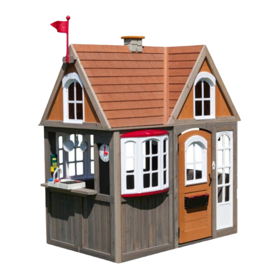
GREYSTONE
COTTAGE
PLAYHOUSE
P280093
INSTALLATION AND OPERATING INSTRUCTIONS
WARNING
OBSTACLE FREE SAFETY ZONE - 19' 1/8" x 16' 3/4" (5.8 x 5.1m)
CAPACITY - 5 Users Maximum, Ages 2 to 10.
RESIDENTIAL HOME USE ONLY. Not intended for public areas such as schools, churches, nurseries, day cares or parks.
WARNING - Only for domestic use.
5.1m
1.1m
5.8m
KidKraft, Inc.
4630 Olin Road
Dallas, Texas 75244 USA
customerservice@kidkraft.com
canadacustomerservice@kidkraft.com
1.800.933.0771
972.385.0100
For online parts replacement visit
https://parts.kidkraft.com/
To reduce the risk of serious injury or death, you must read and follow these instructions.
Keep and refer to these instructions often and give them to any future owner of this play set.
Manufacturer contact information provided below.
1.8m
2
KidKraft Netherlands BV
Olympisch Stadion 8
1076 DE Amsterdam
The Netherlands
europecustomerservice@kidkraft.com
+31 20 305 8620 M-F from 09:00 to 17:30
(GMT+1)
For online parts replacement visit
https://parts.kidkraft.eu/
FOR OUTDOOR FAMILY DOMESTIC USE ONLY
Table of Contents
Warnings and Safe Play Instructions . . . . . . . . . . pg . 2
Instructions for Proper Maintenance . . . . . . . . . pg . 2
Keys to Assembly Success . . . . . . . . . . . . . . . . . . . . pg . 3
About Our Wood - Limited Warranty . . . . . . . . . pg . 4
Battery Instruction and Warranty . . . . . . . . . . . . pg . 5
Keys to Quick Assembly . . . . . . . . . . . . . . . . . . . . . . pg . 6
Part ID . . . . . . . . . . . . . . . . . . . . . . . . . . . . . . . . . . . . . . . pg . 9
Step-By-Step Instructions . . . . . . . . . . . . . . . . . . .pg . 14
Installation of ID/Warning Plaque . . . . . . . . . . .pg . 50
10 - 12 Hrs
10 - 12 Hrs
2-4 Hrs
3 - 5 Hrs
FOR FORT & SWING
FOR FORT & SWING
TWO PERSON
ASSEMBLY
Rev 07/29/2020
Advertisement
Table of Contents

Related Manuals for KidKraft GREYSTONE COTTAGE


Summary of Contents for KidKraft GREYSTONE COTTAGE
-
Page 1: Table Of Contents
KidKraft, Inc. KidKraft Netherlands BV Keys to Assembly Success . . . . . . . . . . . . . . . . . . . . pg . 3... -
Page 2: Warnings And Safe Play Instructions
DO NOT OVER-TIGHTEN. This will cause splintering of wood. If you dispose of your playhouse: Please disassemble and dispose of your unit so that it does not create any unreasonable hazards at the time it is discarded. Be sure to follow your local waste ordinances. europecustomerservice@kidkraft.com... -
Page 3: Keys To Assembly Success
5/16” is slightly Washer larger than 1/4”. Note: Wafer head bolts with blue lock Flat tight or a bolt with a Ny-Lok nut do T-Nut Washer NOT require a lock washer. (Hammer into place) Do not crush wood! europecustomerservice@kidkraft.com... -
Page 4: About Our Wood - Limited Warranty
About Our Wood KidKraft uses only premium playset lumber, ensuring the safest product for your children’s use. Although great care has been taken in selecting the best quality lumber available, wood is a product of nature and susceptible to weathering (changes in the aesthetics of the wood). -
Page 5: Battery Instruction And Warranty
Battery Instruction and Warranty This device complies with Part 15 of the FCC Rules. Operation is subject to the following two conditions: (1) This device may not cause harmful interference, and (2) this device must accept any interference received, including interference that may cause undesired operation. NOTE: This equipment has been tested and found to comply with the limits for a Class B digital device, pursuant to part 15 of the FCC Rules. -
Page 6: Keys To Quick Assembly
The majority of each hardware part comes packed in a separate bag so you do not need to sort the hardware. Each assembly step indicates which hardware (bolt, screw, washer etc.) you will require to complete the step. Instructional video: http://www.kidkraft.eu/stoneycreek-assembly europecustomerservice@kidkraft.com... - Page 7 3320807 3320720 3320335 023 4X 3320542 024 2X 3320334 3200147 3330538 hidden 9207713 9207711 2X 3320742 3320545 9320371...
- Page 8 3330317 3330329 071 6X 072 3X hidden 3320704 3X 3330629 hidden 9320791 9320889 3330909 hidden 3320252 3330908...
-
Page 9: Part Id
Part Identification (Reduced Part Size) Part Identification (Reduced Part Size) Part Identification (Reduced Part Size) Part Identification (Reduced Part Size) 4pc. - 121 - 12.7 x 57.2 x 1063.6mm - Corner Trim FSC- 48046713 (1/2 x 2-1/4 x 41-7/8") 3pc. - 102 - 15.9 x 101.6 x 254mm - Gable Top A FSC - 48081836 3pc. - Page 10 Part Identification (Reduced Part Size) Part Identification (Reduced Part Size) Part Identification (Reduced Part Size) Part Identification (Reduced Part Size) 1pc. - 112 - 23.8 x 63.5 x 127mm - Door Latch Block FSC - 48031913 (15/16 x 2-1/2 x 5") 4pc.
- Page 11 Part Identification (Reduced Part Size) Part Identification (Reduced Part Size) Part Identification (Reduced Part Size) Part Identification (Reduced Part Size) 1pc. - 081 - 31.8 x 836.3 x 939.8mm - Roof Panel - Front Full FSC - 478070006 (1-1/4 x 32-59/64 x 37") (1-1/4 x 18-1/2 x 32-17/64") (1-1/4 x 18-1/2 x 32-17/64") 1pc.
- Page 12 Hardware Identification (Actual Size) 6pc. FW1 - 1/4" Flat Washer - (51103200) 6pc. TN1 - 1/4" T - Nut 6pc. LW1 - 1/4" Lock Washer - (51303200) (54503200) #7 x 5/8" 134pc. S37 - Pan Screw - (52433009) #5 x 3/4" 6pc.
- Page 13 Part Identification (Reduced Part Size) 1x - Door Mount Mailbox Set (3320742) 1x - Chimney Wall (3320807) 1x - Roof Valley III (2 Pk) (3330629) 1x - Playhouse Plaque (9320371) 1x - Door Bell 2/Door Trim (3323645) (3320545) 1x - Deep Window (4Pk) 1x - Clicker Phone &...
-
Page 14: Step-By-Step Instructions
+31 20 305 8620 europecustomerservice@KidKraft.com For online parts replacement visit https://parts.kidkraft.eu/ Read the assembly manual completely, paying special attention to ANSI warnings; notes; and safety/maintenance information on pages 1 - 6. Before you discard your cartons fill out the form below. - Page 15 Step 2: Frame Assembly Part 1 A: Stand (021) Panel Assembly A and (022) Panel Assembly B so that window openings are at the top. (Fig. 2.1 ) B: Flush to the bottom and centred on the Side Walls attach 1 (023) Panel Tie to each wall with 4 (S15) #8 x 1-3/4”...
- Page 16 Step 2: Frame Assembly Part 2 C: From inside the assembly on the right hand side of the door opening, measure 6-11/16” down from the top of the frame and attach 1 Door Hinge using 3 (S39) #5 x ¾” Wood Screws. (Fig. 2.3 and 2.4) D: Measure 5-1/2”...
- Page 17 Step 2: Frame Assembly Part 3 E: Connect Panels A and B using 6 (H2) ¼” x 2” Hex Bolts (with flat washer, lock washer and t-nut) making sure that the hex bolts are installed from inside out on the front wall panel as shown in Fig. 2.5. and 2.6. Fig.
- Page 18 Step 2: Frame Assembly Part 4 F: Attach 1 (023) Panel Tie to Front Door Panel and Back Wide Panel with 4 (S15) #8 x 1-3/4” Wood Screws per board. (Fig. 2.7 ) G: Attach 1 (024) Long Tie to (023) Panel Tie and Front Wall Panel using 4 (S15) #8 x 1-3/4” Wood Screws ensuring that ends are flush.
- Page 19 Step 3: Attach Soffits It is important to note hole orientations for the following steps. A: Flush to the inside face of the Left Side Wall, centre 1 (031) Soffit and attach with 4 (S20) #8 x 1-3/8” Wood Screws. Notice the 2 unused holes on the outside as shown in fig. 3.1 and 3.2. B: Flush to the inside face of the Right Side Wall panel center 1 (034) Soffit Wide and attach using 4 (S20) #8 x 1-3/8”...
- Page 20 Step 4: Café Assembly A: Place (041) Table Top A in the opening of the Left Side Wall Panel so the grooves are tight to the wall and attach with 3 (S15) #8 x 1-3/4” Wood Screws. Repeat step to attach (042) Table Top B to Back Wall Panel and (043) Table Top C to Right Side Wall Panel.
- Page 21 Step 5: Attach Café Accessories Part 1 A: From inside the assembly place 1 Clock Chalk Sign in the side opening of each Side Wall Panel so the top is tight to the opening and attach with 6 (S37) #7 x 5/8” Pan Screws per sign. Repeat for Back Wall Panel. Reverse signs as desired.
- Page 22 Step 5: Attach Café Accessories Part 2 B: From inside the assembly to the left of the window opening on the Back Wall Panel attach 1 Clicker Phone (with holder) using 2 (S37) #7 x 5/8” Pan Screws. (Fig. 5.3) C: On the Right Side Wall Panel from inside the assembly place 1 Hanging Sign to either the left or right side of the window opening and attach with 2 (S0) #8 x 7/8”...
- Page 23 Step 5: Attach Café Accessories Part 3 D: From inside the assembly, centred in the large opening of the Left Side Wall Panel attach Utensil Shelf with 2 (S0) #8 x 7/8” Truss Screws. (Fig. 5.5 and 5.6) E: Attach Pot, Pan and Spatula to the Utensil Shelf. (Fig 5.6) Refer to Step 5 Part 1 for Location Fig.
- Page 24 Step 5: Attach Café Accessories Part 4 F: Place Faucet and 2 Sink Knobs in opening of Sink and attach Sink Knobs with included hardware. (Fig 5.7) Important: Use a hand held screw driver and DO NOT over tighten. G: Centre Sink and Cook Top on (041) Table Top A in the Left Side Wall Panel and attach using 6 (S0) #8 x7/8” Truss Screws.
- Page 25 Step 5: Attach Café Accessories Part 5 Note: Install 2 AAA/LR03 batteries in Doorbell 2 prior to attaching to assembly. To replace batteries remove back cover on Doorbell 2, remove both batteries, insert 2 new batteries ensuring the proper polarity is observed then replace back cover. H: From inside the assembly insert Doorbell 2 into the hole in the Door Wall and attach with 2 (S0) #8 x 7/8”...
- Page 26 Step 6: Bay Window Assembly Part 1 A: From outside the assembly place the Bay Window Bottom in the large opening of the Front Wall Panel and Back Panel as shown in fig. 6.1. Attach using 4 (S37) #7 x 5/8” Pan Screws per panel. Fig.
- Page 27 Step 6: Bay Window Assembly Part 2 B: Bend Folding Bay Window so it is curved and from inside the assembly place into the opening on top of the Bay Window Bottom as shown in fig. 6.2 and 6.4. Attach with 4 (S37) #7 x 5/8” Pan Screws. The sides of the Folding Bay Window Insert should fit tight to the inside of the wall panel.
- Page 28 Step 6: Bay Window Assembly Part 3 D: From outside the assembly place Bay Window Roof on top of Folding Bay Window and under the wall panel then attach to Folding Bay Window with 4 (S37) #7 x 5/8” Pan Screws. (Fig 6.6, 6.7 and 6.8) E: Attach Bay Window Top to the wall panel with 4 (S37) #7 x 5/8”...
- Page 29 Step 7: Roof Support A: Attach one (071) Roof End to a second (071) Roof End at peak using 1 (S3) #8 x 2-1/2” Wood Screw. (Fig. 7.1) B: Place 1 (072) Roof Support Assembly between the Roof Ends so the bottom of the Roof Support Assembly is flush with the bottoms of each Roof End.
- Page 30 Step 8: Roof Assembly Part 1 A: Place (081) Full Roof Panel on its edge so that the overlap is at the top and have a helper hold it. B: Lean (082) Partial Roof Panel Left and (083) Partial Roof Panel Right up against the (081) Full panel so they meet tightly together in the center.
- Page 31 Step 8: Roof Assembly Part 2 C: Place 1 Roof Support against each side of the Roof Panel Assembly so the bottoms are flush and they meet at the peak. (Fig. 8.4) Attach using 6 (S11) #8 x 2” Wood Screws per End Assembly. (Fig. 8.3) Fig.
- Page 32 Step 8: Roof Assembly Part 3 D: With a helper, lift the Roof Assembly and place it onto the far right hand side of the Playhouse so that the Roof Assembly sits flush with soffits. Attach the Roof Assembly from underneath the 4 corners using 4 (S20) #8 x 1-3/8”...
- Page 33 Step 8: Roof Assembly Part 4 E: Use 4 (S3) #8 x 2-1/2” Wood Screws to secure (072) Roof Support Assembly. (Fig. 8.10 and 8.11) Fig. 8.10 x 2 per Roof Support Fig. 8.11 Hardware #8 x 2-1/2” Wood Screw...
- Page 34 Step 9: Roof Valley Assembly Part 1 A: From inside the assembly place 1 Roof Valley 3 tight against each Partial Panel so each Roof Valley extends past the outer face of the panel and attach using 9 (S37) #7 x 5/8” Pan Screws. (Fig 9.1, 9.2 and 9.3) Fig.
- Page 35 Step 9: Roof Valley Assembly Part 2 B: Attach (092) Half Roof Right Panel to (091) Half Roof Left Panel using 2 (S11) #8 x 2” Wood Screws making sure that the (092) Half Roof Right is overlapping the (091) Half Roof Left. (Fig. 9.4, 9.5 and 9.6) Fig.
- Page 36 Step 9: Roof Valley Assembly Part 3 C: Place the Half Roof Panel Assembly onto the Playhouse so that the back of the assembly is tight to the roof assembly and rests on each Roof Valley 3. (Fig. 9.7) D: Attach the Half Roof Panel Assembly to Roof Valley using 12 (S37) #7 x 5/8” Pan Screws. (Fig. 9.8) Fig.
- Page 37 Step 9: Roof Valley Assembly Part 4 E: Place the final Roof End Assembly against the Half Roof Panel Assembly ensuring that it is flush. Attach using 6 (S11) #8 x 2” Wood Screws in the (071) Roof Ends and 4 (S20) #8 x 1-3/8” Wood Screws from the underside of the soffits into the (072) Roof Support Assembly and (071) Roof Ends.
- Page 38 Step 10: Gable Assembly Part 1 A: From inside the assembly, tight to the top of the roof assembly attach (101) Gable Top B using 4 (S20) #8 x 1-3/8” Wood Screws. (Fig. 10.1 and 10.2) B: Tight to (101) Gable Top B attach (102) Gable Top A with 4 (S20) #8 x 1-3/8” Wood Screws. (Fig. 10.1 and 10.2) C: Repeat steps for remaining 2 Gables.
- Page 39 Step 10: Gable Assembly Part 2 D: Vertically, on either side of (102) Gable Top A attach 1 (103) Gable Side A with 6 (S15) #8 x 1-3/4” Wood Screws. Measure to ensure that there is a 10” opening for the window. (Fig. 10.3 and 10.4) Fig.
- Page 40 Step 10: Gable Assembly Part 3 E: Attach remaining (104) Gable Side B and (105) Gable Side C boards using 14 (S20) #8 x 1-3/8” Wood Screws. (Fig. 10.5 and 10.6) F: Repeat steps for remaining 2 Gables. Fig. 10.5 Fig.
- Page 41 Step 11: Attach Door Panel Accessories Part 1 A: Measure 18-1/4” up from the bottom of the (111) Door Assembly on the outside and inside and attach 1 Door Handle per side using 2 (S37) #7 x 5/8” Pan Screws per handle. (Fig. 11.1 and 11.2) B: Measure 15”...
- Page 42 Step 11: Attach Door Panel Accessories Part 2 C: In the opening for the door measure 5/8” up from the bottom and attach (111) Door Assembly to hinges using 3 (S37) #7 x 5/8” Pan Screws per hinge. (Fig. 11.3, 11.4 and 11.5) Fig.
- Page 43 Step 11: Attach Door Panel Accessories Part 3 D: In the notched out opening of (112) Door Latch Block attach the Magnetic Catch using 2 (S38) #7 x 1-1/8” Pan Screws. (Fig. 11.6) Important: Use a hand held screw driver and DO NOT over tighten. E: From inside the assembly centre (112) Door Latch Block on Catch Plate so the Magnetic Catch and the Catch Plate can connect then attach to Door Wall with 2 (S15) #8 x 1-3/4”...
- Page 44 Step 11: Attach Door Panel Accessories Part 4 F: On the outside face of the (111) Door Assembly place 1 Deep Window in the window gap and attach with 4 (S37) #7 x 5/8” Pan Screws. Repeat step for remaining 3 Deep Windows. (Fig. 11.8 and 11.9) Fig.
- Page 45 Step 11: Attach Door Panel Accessories Part 5 G: On the top slat of the door panel, below the window attach the Door Mount Mail Box using 4 (S37) #7 x 5/8” Pan Screws. (Fig. 11.10) Fig. 11.10 Door Panel Door Mount Mailbox Other Parts Hardware...
- Page 46 Step 12: Attach Corner Trim A: On the Right Side Panel place 2 pieces of (121) Corner Trim on either side of the panel, flush to the outside edge. Attach using 6 (S38) #7 x 1-1/8” Pan Screws per Trim piece. (Fig. 12.1 and 12.2) B: On the Front Wall Panel place 1 (121) Corner Trim alongside the Bay Window and flush to the outside edge of the panel.
- Page 47 Step 13: Chimney Assembly Part 1 A: Bend the Chimney Wall to form a box and insert tabs into slots. (Fig. 13.1 and 13.2) B: Place the (131) Chimney Top on top of the assembly and attach with 2 (S37) #7 x 5/8” Pan Screws. (Fig. 13.2, 13.3 and 13.4) Fig.
- Page 48 Step 13: Chimney Assembly Part 2 C: On top of the Roof Assembly measure 24-1/2” in from Side Wall then place the Chimney Wall Assembly on top of the Roof Assembly as shown in fig. 13.5 and attach with 2 (S37) #7 x 5/8” Pan Screws. (Fig. 13.6) Chimney Wall Assembly Fig.
- Page 49 Step 14: Attach Flag A: Insert 1 Flag into slots on 1 Flag Pole to complete 1 Deluxe Flying Flag as shown in Fig. 14.1. B: Place (141) Flag Block to the top corner of the Gable, ensure that the edges are flush with the (071) Roof Ends.
-
Page 50: Installation Of Id/Warning Plaque
Final Step: Attach Playhouse Plaque A: To the right of the door, on the top right hand corner of the narrow window panel install the Playhouse Plaque with 2 (S37) #7 x 5/8” Pan Screws. (Fig. 15.1 and 15.2) Fig. 15.2 attach plaque to playhouse with 2 S37 (#7 x 5/8"... - Page 51 NOTES...
- Page 52 Would you recommend the purchase of our products to friends and family? Comments: MAIL TO: Fill out your registration card online at KidKraft https://prdregistration.kidkraft.com/ 4630 Olin Road Dallas, TX 75244 United States KidKraft would like to say Thank You for Attention: Customer Service your time and feedback.
Need help?
Do you have a question about the GREYSTONE COTTAGE and is the answer not in the manual?
Questions and answers