Table of Contents
Advertisement
Quick Links
Gearless Lift Machine
WSG-W8
Operating Instructions
Reprinting, translation or reproduction in any form -
whether in part or in full - requires the prior written
permission of WITTUR Holding GmbH.
Änderungen vorbehalten!
Gearless Lift Machines
beamer 2
WSG-W8.3
WSG-W8.4
WITTUR Holding GmbH
Rohrbachstraße 26-30 • D-85259 Wiedenzhausen, Germany
Tel. +49 (0) 81 34/18-0 • Fax +49 (0) 81 34/18-49
http://www.wittur.com, E-mail: info@wittur.com
Seite/page
Datum/date
Stand/version
Wittur Holding GmbH reserves the right to make
changes in the information and pictures contained in
these operating instructions without prior notice.
Subject to changes without notice!
1
29.01.2010
0.13
Advertisement
Table of Contents

Subscribe to Our Youtube Channel
Related Manuals for WITTUR WSG-W8 Series


Summary of Contents for WITTUR WSG-W8 Series
- Page 1 Tel. +49 (0) 81 34/18-0 • Fax +49 (0) 81 34/18-49 http://www.wittur.com, E-mail: info@wittur.com Reprinting, translation or reproduction in any form - Wittur Holding GmbH reserves the right to make whether in part or in full - requires the prior written changes in the information and pictures contained in permission of WITTUR Holding GmbH.
- Page 2 These operating instructions are applicable to lift machines: WSG - W8..WITTUR Electric Drives GmbH reserves the right to correct or change the contents of this manual and these product details without prior notice. expressly reserve the right to make technical changes which improve the lift machines or their safety stan- dards without prior notice.
-
Page 3: Table Of Contents
Gearless Lift Machine Seite/page Datum/date 29.01.2010 WSG-W8 Stand/version 0.13 Operating Instructions Contents 1. General safety instructions........................4 2. Product description...........................6 3. Nameplate..............................8 4. Scope of supply ............................9 5. Transport and storage ..........................9 6. Installation..............................10 7. Electrical connection ..........................12 7.1. General ................12 7.2. -
Page 4: General Safety Instructions
Gearless Lift Machine Seite/page Datum/date 29.01.2010 WSG-W8 Stand/version 0.13 Operating Instructions 1. General safety instructions Explanation of symbols used in these instructions • Non-compliance with the instructions contained in the operating instructions or other documentation sup- means that death or serious injury to per- plied sons or serious damage to property will •... - Page 5 Gearless Lift Machine Seite/page Datum/date 29.01.2010 WSG-W8 Stand/version 0.13 Operating Instructions • Repairs may only be carried out by the manufacturer or an authorised repair agency. Unauthorised opening and tam- pering may result in injuries to persons and property. • The machines are not designed for direct connection to the three-phase system but are to be operated via an electronic...
-
Page 6: Product Description
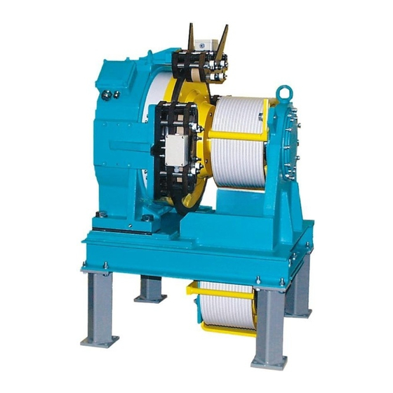
Gearless Lift Machine Seite/page Datum/date 29.01.2010 WSG-W8 Stand/version 0.13 Operating Instructions 2. Product description The series WSG-W8 is a complete drive system, including The motor is electrically connected in the terminal box a base frame (1), an integrated drive motor (2) and a (16), where the connection for the temperature monito- secondary sheave system (3) for the preferred option of ring device is also located. - Page 7 Gearless Lift Machine Seite/page Datum/date 29.01.2010 WSG-W8 Stand/version 0.13 Operating Instructions Subject to changes without notice! Änderungen vorbehalten!
-
Page 8: Nameplate
Gearless Lift Machine Seite/page Datum/date 29.01.2010 WSG-W8 Stand/version 0.13 Operating Instructions The adjustment is made by displacing the secondary sheave on the shaft after loosening the adjusting rings. The offset a /2 between the traction and secondary sheaves is necessary to compensate the deflections resulting from the rope being led in a spiral as shown in the figure "... -
Page 9: Scope Of Supply
Gearless Lift Machine Seite/page Datum/date 29.01.2010 WSG-W8 Stand/version 0.13 Operating Instructions 4. Scope of supply • Lift machine WSG-W8 according to order specification Options: • Operating instructions • Release lever set with remotely controlled bowden cable • Screws for disassembly the brake •... -
Page 10: Installation
Gearless Lift Machine Seite/page Datum/date 29.01.2010 WSG-W8 Stand/version 0.13 Operating Instructions 6. Installation Be sure to check the base frame or founda- The torque and power values indicated in the Technical tion loads by calculation before installing Data apply to the above ambient temperatures and alti- the lift machine. - Page 11 Gearless Lift Machine Seite/page Datum/date 29.01.2010 WSG-W8 Stand/version 0.13 Operating Instructions Subject to changes without notice! Änderungen vorbehalten!
-
Page 12: Electrical Connection
Gearless Lift Machine Seite/page Datum/date 29.01.2010 WSG-W8 Stand/version 0.13 Operating Instructions 7. Electrical connection 7.1. General 7.2. Motor connection / Winding protection The electrical connection may only be made The electrical connection of the motor and the winding by a qualified electrician. monitoring devices is made in the terminal box on top of the machine. - Page 13 Gearless Lift Machine Seite/page Datum/date 29.01.2010 WSG-W8 Stand/version 0.13 Operating Instructions Handling Motor connection diagram M 20 für Kabeldurchmesser 7-12 mm M 20 • Hold the bared con- for cable diameter ductor against the 7-12 mm W1 V1 U1 2 1 terminal.
- Page 14 Gearless Lift Machine Seite/page Datum/date 29.01.2010 WSG-W8 Stand/version 0.13 Operating Instructions Earthing For safety reasons, it is very important that the motor be properly and carefully earthed. It is essential to use the earthing terminal in the terminal box. In addition, an earth- ing screw is provided on the motor frame for the connection of a protective or earth- Warning...
-
Page 15: Speed/Position Measuring System
Gearless Lift Machine Seite/page Datum/date 29.01.2010 WSG-W8 Stand/version 0.13 Operating Instructions 7.3. Speed/Position measuring system 7.3.1. Measuring system ECN 1313 Number of sine-cosine The basic version of the lift machines is equipped with a periods per rotation: 2048 ECN 1313 sine-cosine encoder from Heidenhain GmbH. Operating voltage: The encoder is connected via a 17-pole signal plug con- nector which is fitted to the measuring system housing. -
Page 16: Brake
Gearless Lift Machine Seite/page Datum/date 29.01.2010 WSG-W8 Stand/version 0.13 Operating Instructions 7.4. Brake The switches must be evaluated separately for each partial brake to ensure compliance The brakes are supplied with d.c. voltage by an overexci- with the requirements of the type examina- tation rectifier which is installed in the terminal box for Danger tion. - Page 17 Gearless Lift Machine Seite/page Datum/date 29.01.2010 WSG-W8 Stand/version 0.13 Operating Instructions Circuitry suggestion for brake control Subject to changes without notice! Änderungen vorbehalten!
-
Page 18: Commissioning
Gearless Lift Machine Seite/page Datum/date 29.01.2010 WSG-W8 Stand/version 0.13 Operating Instructions 8. Commissioning The following points should be checked or completed: • Remove all securing, auxiliary and installation tools from the danger area. • Check that the lift machine is used for its intended purpose and that the permissible ambient conditions are met. -
Page 19: Operation And Maintenance
Gearless Lift Machine Seite/page Datum/date 29.01.2010 WSG-W8 Stand/version 0.13 Operating Instructions 9. Operation and maintenance 9.1. General 9.2. Maintenance intervals The regulations concerning operation, maintenance and Check the thickness every six inspection in accordance with the applicable safety regu- see section 9.6. of the brake linings months lations in lift construction such as DIN EN 81 "Safety rules... -
Page 20: Lubricating Instructions
Gearless Lift Machine Seite/page Datum/date 29.01.2010 WSG-W8 Stand/version 0.13 Operating Instructions 9.3. Lubricating instructions Observe a high standard of cleanliness when doing this The two traction sheave main bearings (internal and work, to prevent any foreign material, dirt or dangerous external self-aligning roller bearings 10 and 12 in the liquids from penetrating into the bearings. - Page 21 Gearless Lift Machine Seite/page Datum/date 29.01.2010 WSG-W8 Stand/version 0.13 Operating Instructions The brake lever plates and the asso- WSG- ciated counter plates also have holes and slots to which Bowden cables W8.3 W8.4 (two brakes) (three brakes) can be attached. By using special Item in lever devices, the brakes can then also be released remotely by hand or...
- Page 22 Gearless Lift Machine Seite/page Datum/date 29.01.2010 WSG-W8 Stand/version 0.13 Operating Instructions Installation of the manual brake releasing device In the very rare case of load compensation between the car and the counterweight, the electric return motion control must be used. When required and if expressly ordered, the attachable manual turning device No.
-
Page 23: Replacing The Traction Sheave
Gearless Lift Machine Seite/page Datum/date 29.01.2010 WSG-W8 Stand/version 0.13 Operating Instructions now self-supported on the shaft, proceed to the accurate positioning and securing of the stop plate. To this end, screw in the two M16x35 hexagon head bolts (42) and tighten the centre bolt (41) alternately. -
Page 24: Replacing The Brakes
Gearless Lift Machine Seite/page Datum/date 29.01.2010 WSG-W8 Stand/version 0.13 Operating Instructions 9.6. Replacing the brakes Disassembly • Remove the two M6 x 40 spring bolts. • Release the brake manually using the two M6 x 65 release screws supplied (see figure). Release screws be Ensure the brake unit is not dropped. -
Page 25: Switch-Adjusting For Monitoring The Brake
Gearless Lift Machine Seite/page Datum/date 29.01.2010 WSG-W8 Stand/version 0.13 Operating Instructions 9.7. Switch-adjusting for monitoring the brake • Remove the brake terminal box (A) • Check that the switch-point is between s = 0 mm and 0.3 mm. • Switch on the brake magnet; s has to be 0 mm. -
Page 26: Replacing The Measuring System
Gearless Lift Machine Seite/page Datum/date 29.01.2010 WSG-W8 Stand/version 0.13 Operating Instructions 9.9. Replacing the measuring system The measuring system is only accessible from the rear side of the motor. Spannring am Mess-System Note clamping ring on Disassemble the measuring system only if measuring system this is necessary because of a defect. -
Page 27: Trouble Shooting
Gearless Lift Machine Seite/page Datum/date 29.01.2010 WSG-W8 Stand/version 0.13 Operating Instructions 9.10. Trouble shooting Fault Possible cause Remedy Motor does not start, operates out of • Motor not connected in proper • Connect motor correctly phase sequence control or develops no torque •... -
Page 28: Type Code
Gearless Lift Machine Seite/page Datum/date 29.01.2010 WSG-W8 Stand/version 0.13 Operating Instructions 10. Type code Example: G- W8 . 4 0 A G- W8 . Z3 - X3 X4 X5 X6 X7 X8 X9 Customer specific identifier S = Synchronous motor G = Gearless Frame size Z3: Overall length:... -
Page 29: Technical Data
Gearless Lift Machine Seite/page Datum/date 29.01.2010 WSG-W8 Stand/version 0.13 Operating Instructions 11. Technical data Duty type: S3 - 40 % ED caliper disk brake Traction sheave: dia. 400 mm or dia. 320 mm WSG-W8.3 WSG-W8.4 Traction sheave hardnesse: min. 220 HB 30 Type: BFK 466-55 Typical number of carry-... - Page 30 Gearless Lift Machine Seite/page Datum/date 29.01.2010 WSG-W8 Stand/version 0.13 Operating Instructions synchron / synchronous 22-polig / 22-poles WSG-W8.3 WSG-W8.4 Motor / motor Drehmoment / torque 1100 [Nm] S3-40%, 240 S/h Æ D Treibscheibe / traction sheave [mm] Æ D Gegenscheibe / secondary sheave [mm] 1400 1150...
-
Page 31: Dimension Drawing
Gearless Lift Machine Seite/page Datum/date 29.01.2010 WSG-W8 Stand/version 0.13 Operating Instructions 12. Dimension drawing Execution examples: Trägheitsmoment Masse Æ D / Æ D inertia weight Motor / motor Typschlüssel Æ D / Æ D [kgm [kg] Type code X5 X6 X7 WSG-W8.3 320 / 320 320 / 320... - Page 32 Gearless Lift Machine Seite/page Datum/date 29.01.2010 WSG-W8 Stand/version 0.13 Operating Instructions Rahmen- Motor frame motor The WSG-W8 lift machine comprises a com- pact frame motor, an adaptable secondary sheave block and optional feet. The secondary sheave block can be fitted offset from the machine centre either to the right ("+"...
-
Page 33: Accessories
Gearless Lift Machine Seite/page Datum/date 29.01.2010 WSG-W8 Stand/version 0.13 Operating Instructions 13. Accessories 13.1. Connecting cable for measuring systems recom. recommended Inverter type encoder system measurement system cable ECN 1313 502 452 021 xx unidrive SP (EnDat or SSI) emotron/ ECN 1313 Dietz 501 112 022 xx... -
Page 34: Cable Set For Motor And Brake
Gearless Lift Machine Seite/page Datum/date 29.01.2010 WSG-W8 Stand/version 0.13 Operating Instructions 13.2. Cable set for motor and brake Subject to changes without notice! Änderungen vorbehalten! -
Page 35: Release Lever Set With Remotely Controlled Bowden Cable
Gearless Lift Machine Seite/page Datum/date 29.01.2010 WSG-W8 Stand/version 0.13 Operating Instructions 13.3. Release lever set with remotely controlled 13.4. Rubber cushions Bowden cable The remote control of the brake by Bowden cable is used to release the brakes mechanically in the case of an emergency. -
Page 36: Spare Parts
Gearless Lift Machine Seite/page Datum/date 29.01.2010 WSG-W8 Stand/version 0.13 Operating Instructions 14. Spare parts Item Part Description Motor Rope slip-off guard 505 284 Hydraulic-type lubricating nipple DIN 71 412 - AM 10 x 1 Dummy stopper N-Pg 9 DIN 46320-Fs Rope slip-off guard, cpl. -
Page 37: Ec Type-Examination Certificate
Gearless Lift Machine Seite/page Datum/date 29.01.2010 WSG-W8 Stand/version 0.13 Operating Instructions 15. EC type-examination certificate Subject to changes without notice! Änderungen vorbehalten! - Page 38 Gearless Lift Machine Seite/page Datum/date 29.01.2010 WSG-W8 Stand/version 0.13 Operating Instructions Subject to changes without notice! Änderungen vorbehalten!
- Page 39 Gearless Lift Machine Seite/page Datum/date 29.01.2010 WSG-W8 Stand/version 0.13 Operating Instructions Subject to changes without notice! Änderungen vorbehalten!
- Page 40 (undersigned, title) (undersigned, title) WITTUR Electric Drives GmbH • Offenburger Str. 3 • D-01189 Dresden Tel.: +49 (0) 351 40 44-0 • Fax: +49 (0) 351 40 44-111 • www.wittur-edrives.de • info@wittur-edrives.de Subject to changes without notice! Änderungen vorbehalten! Amtsgericht Dresden • HRB 14244 • USt-IdNr. DE 812179588 • Geschäftsführer: Dr. Peter Sekula Ostsächsische Sparkasse Dresden •...
Need help?
Do you have a question about the WSG-W8 Series and is the answer not in the manual?
Questions and answers