Table of Contents
Advertisement
Quick Links
OPERATING INSTRUCTIONS
WSG-25
GEARLESS LIFT MACHINE
No part of this publication may be reproduced
or translated, even in part, without prior written
permission from WITTUR.
Subject to change without notice!
www.wittur.com
Translation of the Original Operating Instructions
Nachdruck, Übersetzung und Vervielfältigung in
jeglicher Form - auch auszugsweise - bedürfen der
schriftlichen Genehmigung von WITTUR.
Änderungen vorbehalten!
Code
GM.8.002673.EN
Version
0.13a
Date
07. May 2019
info.wed@wittur.com
www.wittur.com
© Copyright WITTUR 2019
Advertisement
Chapters
Table of Contents

Subscribe to Our Youtube Channel
Related Manuals for WITTUR WSG-25


Summary of Contents for WITTUR WSG-25
- Page 1 Nachdruck, Übersetzung und Vervielfältigung in info.wed@wittur.com or translated, even in part, without prior written jeglicher Form - auch auszugsweise - bedürfen der www.wittur.com permission from WITTUR. schriftlichen Genehmigung von WITTUR. © Copyright WITTUR 2019 Subject to change without notice! Änderungen vorbehalten! www.wittur.com...
- Page 2 WSG - 25.1- ..WSG - 25.2- ..date: 07. May 2019 version: 0.13a WITTUR Electric Drives GmbH reserves the right to correct or change the contents of this manual and these product details without prior notice. We expressly reserve the right to make technical changes which improve the lift machines or their safety standards without prior notice.
-
Page 3: Table Of Contents
8.5. Individual check of the brake function 8.6. Replacing the measuring system 9. Technical data 10. Dimension drawing WSG-25.1/2 with traction sheave dia. 530 mm 11. Dimension drawing WSG-25.1/2 with traction sheave dia. 650 mm 12. Accessories 12.1. Connecting cable for measuring systems for ECN 1313 and ERN 1387 12.2. -
Page 4: General Information
General information 1.1. About this operating manual The purpose of this operating manual is to ensure that any work on WSG-25 lift machines is carried out safely. Please regard it as part of the product and keep it within easy reach. -
Page 5: Safety
Gearless Lift Machine Code: GM.8.002673.EN WSG-25 Date: 07. May 2019 Version: 0.13a Operating Instructions Page: Safety 2.1. General safety instructions 2.1.1. Qualified personnel Only qualified personnel are authorised to perform any planning, installation or maintenance work, and this must be done in accordance with the relevant instructions. -
Page 6: Eu Declaration Of Conformity
Gearless Lift Machine Code: GM.8.002673.EN WSG-25 Date: 07. May 2019 Version: 0.13a Operating Instructions Page: EU Declaration of Conformity Subject to changes without notice ! Änderungen vorbehalten ! -
Page 7: Handling
Gearless Lift Machine Code: GM.8.002673.EN WSG-25 Date: 07. May 2019 Version: 0.13a Operating Instructions Page: Handling 4.1. Transport and storage • Climate class: 2K3 according EN 60721 • Transport temperature: -20°C bis +60°C, max. 20 K/hour fluctuated • Transport air humidity: max. relative humidity 85 % at 20°C (no moisture condensation) •... -
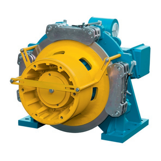
Page 8: Product Overview
Product overview 5.1. Product description The compact gearless WSG-25 synchronous lift machines are designed for traction sheave lifts. They are distinguished by their high efficiency, extremely low noise and excellent operating characteristics. The machines can be supplied for several rated speeds. -
Page 9: Permissible Ambient Conditions
Gearless Lift Machine Code: GM.8.002673.EN WSG-25 Date: 07. May 2019 Version: 0.13a Operating Instructions Page: 5.2. Permissible ambient conditions • Ambient temperature: -5°C to +40°C • Air humidity: max. relative humidity: 85% at 20°C (no moisture condensation) • Install the machine so that ventilation is not obstruct and sufficient heat dissipation by convection and radiation must be ensured. -
Page 10: Motor Connection / Winding Protection / Fan
Gearless Lift Machine Code: GM.8.002673.EN WSG-25 Date: 07. May 2019 Version: 0.13a Operating Instructions Page: 5.3.2. Motor connection / Winding protection / Fan • The electrical connection of the motor, the fan and the winding sensors is made in the motor terminal box on the machine. -
Page 11: Speed/Position Measuring System
• To achieve the maximum precision, the measurement voltage per PTC thermistor must not exceed 2.5 V DC. Short-circuiting the motor terminals • The motor terminals of the synchronous lift machines, type WSG-25, can be short-circuited, if required, to brake the lift machine faster. -
Page 12: Brake
Gearless Lift Machine Code: GM.8.002673.EN WSG-25 Date: 07. May 2019 Version: 0.13a Operating Instructions Page: 5.3.4. Brake • Please refer also to the operating instructions for the brake starting on page 47. • The brakes are supplied with DC voltage by the brake control units, which are fitted in the brake terminal box. - Page 13 Gearless Lift Machine Code: GM.8.002673.EN WSG-25 Date: 07. May 2019 Version: 0.13a Operating Instructions Page: Connection of the brakes The brake coils, the brake control units and the monitoring contacts are connected to the mains in the brake terminal box.
- Page 14 Gearless Lift Machine Code: GM.8.002673.EN WSG-25 Date: 07. May 2019 Version: 0.13a Operating Instructions Page: Circuitry suggestion for brake control Subject to changes without notice ! Änderungen vorbehalten !
-
Page 15: Type Code
Gearless Lift Machine Code: GM.8.002673.EN WSG-25 Date: 07. May 2019 Version: 0.13a Operating Instructions Page: 5.5. Type code Example: 6 5 A Customer specific identifier Z1 Z2 X3 X4 / X5 X6 X7 - X8 X9 S: Synchronous motor G = gearless U = gearless;... -
Page 16: Installation
Gearless Lift Machine Code: GM.8.002673.EN WSG-25 Date: 07. May 2019 Version: 0.13a Operating Instructions Page: Installation 6.1. Mechanical installation Setting up f Be sure to use calculations to check the base frame or foundation loads before installing the lift machine. -
Page 17: Electrical Installations
Gearless Lift Machine Code: GM.8.002673.EN WSG-25 Date: 07. May 2019 Version: 0.13a Operating Instructions Page: 6.2. Electrical installations f The electrical installation may only be carried out by trained and qualified personnel with professional knowledge of electrical engineering. DANGER • Before starting any work on the machines, ensure that the lift machine or system is properly isolated. -
Page 18: Commissioning And Operating
Gearless Lift Machine Code: GM.8.002673.EN WSG-25 Date: 07. May 2019 Version: 0.13a Operating Instructions Page: Commissioning and operating 7.1. Important notes f The commissioning may only be carried out by trained and qualified personnel with professional knowledge of electrical engineering and lift construction. -
Page 19: Emergency Evacuation
Gearless Lift Machine Code: GM.8.002673.EN WSG-25 Date: 07. May 2019 Version: 0.13a Operating Instructions Page: 7.2. Emergency evacuation f All actions for evacuation in case of emergency have to be done by qualified service personnel. f When attempting an evacuation, the car may not move even when the brakes are released, as a result of load compensation between the car and the counterweight. -
Page 20: Testing The Brake System To En
Gearless Lift Machine Code: GM.8.002673.EN WSG-25 Date: 07. May 2019 Version: 0.13a Operating Instructions Page: Mechanical return motion device • For cases such as lift failure or the car being retained by the safety device, a mechanical return motion device can be used to move the lift manually. -
Page 21: Trouble Shooting
Gearless Lift Machine Code: GM.8.002673.EN WSG-25 Date: 07. May 2019 Version: 0.13a Operating Instructions Page: 7.4. Trouble shooting Fault Possible cause Remedy Motor does not start, operates out of Motor not connected in proper phase Connect motor correctly control or develops no torque... -
Page 22: Maintenance
Gearless Lift Machine Code: GM.8.002673.EN WSG-25 Date: 07. May 2019 Version: 0.13a Operating Instructions Page: Maintenance 8.1. General • The regulations concerning operation, maintenance and inspection pursuant to the applicable safety regula tions for lift construction such as DIN EN 81-20, DIN EN 81-50, LD 2014/33/EU and other relevant regulations are to be strictly observed. -
Page 23: Regreasing The Bearings
Gearless Lift Machine Code: GM.8.002673.EN WSG-25 Date: 07. May 2019 Version: 0.13a Operating Instructions Page: 8.3. Regreasing the bearings Relubricate the main bearing after about 7,000 hours of operation or every 3 years, using a KP 2 N-30 to DIN 51 502 grease such as Wälalit LZ 2 or Klüberlub BE 41-542 (approx. -
Page 24: Fan Filter Mats
Gearless Lift Machine Code: GM.8.002673.EN WSG-25 Date: 07. May 2019 Version: 0.13a Operating Instructions Page: Extraction of the grease With the re-lubrication the old or surplus grease is pressed in a collector duct. The collector duct is big enough to catch grease of 12…15 proper re-lubrications and is therefore sufficient for the lifetime of the machine. -
Page 25: Individual Check Of The Brake Function
Gearless Lift Machine Code: GM.8.002673.EN WSG-25 Date: 07. May 2019 Version: 0.13a Operating Instructions Page: 8.5. Individual check of the brake function Only perform this test if necessary, e.g. after an emergency evacuation by mechanical manual means. f All work on the brakes may only be carried out when the lift system is at a standstill. Unit power-off. Lock out and tag out. -
Page 26: Replacing The Measuring System
Gearless Lift Machine Code: GM.8.002673.EN WSG-25 Date: 07. May 2019 Version: 0.13a Operating Instructions Page: 8.6. Replacing the measuring system f The measuring system is only accessible from the rear side of the motor. f See the mounting instructions for the Heidenhain encoder. -
Page 27: Technical Data
Gearless Lift Machine Code: GM.8.002673.EN WSG-25 Date: 07. May 2019 Version: 0.13a Operating Instructions Page: Technical data General Dual-circuit fail-safe brake Duty type: Motor: WSG-25.1/2 (S3-40% ED) Traction sheave: dia. 530 mm or dia. 650 mm Brake type: BFK 466-61 Traction sheave hardness: mind. -
Page 28: Dimension Drawing Wsg-25.1/2 With Traction Sheave Dia. 530 Mm
Gearless Lift Machine Code: GM.8.002673.EN WSG-25 Date: 07. May 2019 Version: 0.13a Operating Instructions Page: 10. Dimension drawing WSG-25.1/2 with traction sheave dia. 530 mm Subject to changes without notice ! Änderungen vorbehalten ! -
Page 29: Dimension Drawing Wsg-25.1/2 With Traction Sheave Dia. 650 Mm
Gearless Lift Machine Code: GM.8.002673.EN WSG-25 Date: 07. May 2019 Version: 0.13a Operating Instructions Page: 11. Dimension drawing WSG-25.1/2 with traction sheave dia. 650 mm Subject to changes without notice ! Änderungen vorbehalten ! -
Page 30: Accessories
Gearless Lift Machine Code: GM.8.002673.EN WSG-25 Date: 07. May 2019 Version: 0.13a Operating Instructions Page: 12. Accessories 12.1. Connecting cable for measuring systems for ECN 1313 and ERN 1387 Recommended Recommended Inverter type encoder system measurement system cable F-Pack ECN 1313 - EnDat... -
Page 31: Cable Set For Motor And Brake
Gearless Lift Machine Code: GM.8.002673.EN WSG-25 Date: 07. May 2019 Version: 0.13a Operating Instructions Page: 12.2. Cable set for motor and brake • KS 503 653 E21 - xx - motor cable 4 x 16 mm • KS 503 653 H21 - xx - motor cable 4 x 50 mm with xx...cable length [m]... -
Page 32: Remote Brake Control By Bowden Cable
Gearless Lift Machine Code: GM.8.002673.EN WSG-25 Date: 07. May 2019 Version: 0.13a Operating Instructions Page: 12.4. Remote brake control by Bowden cable The Bowden cable remote control is used to release the brakes mechanically in the event of an emergency. See section 7.2. - Page 33 Gearless Lift Machine Code: GM.8.002673.EN WSG-25 Date: 07. May 2019 Version: 0.13a Operating Instructions Page: 4. Tension the Bowden cables on the lever block (1) using the nuts (10 and 11) on the threaded rod (12). The manual release levers (4) of the brakes (3) must not move.
-
Page 34: Installation When Retrofitting Systems
Gearless Lift Machine Code: GM.8.002673.EN WSG-25 Date: 07. May 2019 Version: 0.13a Operating Instructions Page: 12.4.2. Installation when retrofitting systems f Lock the car and the counterweight and ensure that all of the necessary safety precautions are observed for the lift system. - Page 35 Gearless Lift Machine Code: GM.8.002673.EN WSG-25 Date: 07. May 2019 Version: 0.13a Operating Instructions Page: 5. Perform at least three functional tests by actuating 260 N the lever (9) on the lever block (1) until the brakes are released. (Make a visual check of the brake air gap; check that the traction sheave can turn freely.)
-
Page 36: Return Motion Device
Gearless Lift Machine Code: GM.8.002673.EN WSG-25 Date: 07. May 2019 Version: 0.13a Operating Instructions Page: 12.5. Return motion device f Only qualified service personnel are permitted to take any evacuation measures in the event of an emergency. DANGER The return motion device is used to... - Page 37 Gearless Lift Machine Code: GM.8.002673.EN WSG-25 Date: 07. May 2019 Version: 0.13a Operating Instructions Page: 5. Insert the threaded rod (1) into the bearing block (8) and fasten it using the nut (7). Ensure that the nut (7) is completely screwed onto the threaded rod (1) with 2-4 mm of thread left protruding beyond the nut.
-
Page 38: Spare Parts
Gearless Lift Machine Code: GM.8.002673.EN WSG-25 Date: 07. May 2019 Version: 0.13a Operating Instructions Page: 13. Spare parts Item Part Description Motor traction sheave acc. machine nameplate type code X5 X6 X7 measuring system (depending on spec.) Brake system overexcitation rectifier... -
Page 39: Annex
Gearless Lift Machine Code: GM.8.002673.EN WSG-25 Date: 07. May 2019 Version: 0.13a Operating Instructions Page: 14. Annex Calculation of the traction sheave shaft WSG-25 Subject to changes without notice ! Änderungen vorbehalten ! - Page 40 Gearless Lift Machine Code: GM.8.002673.EN WSG-25 Date: 07. May 2019 Version: 0.13a Operating Instructions Page: Subject to changes without notice ! Änderungen vorbehalten !
-
Page 41: Eu Type-Examination Certificate Eu-Bd 908
Gearless Lift Machine Code: GM.8.002673.EN WSG-25 Date: 07. May 2019 Version: 0.13a Operating Instructions Page: EU type-examination Certificate EU-BD 908 Subject to changes without notice ! Änderungen vorbehalten ! - Page 42 Gearless Lift Machine Code: GM.8.002673.EN WSG-25 Date: 07. May 2019 Version: 0.13a Operating Instructions Page: Annex to the EC Type-Examination Certificate No. EU-BD 908 of 2016-03-18 Scope of application Use as braking device – part of the the protection device against overspeed for the car mov- ing in upwards direction –...
- Page 43 Gearless Lift Machine Code: GM.8.002673.EN WSG-25 Date: 07. May 2019 Version: 0.13a Operating Instructions Page: Annex to the EC Type-Examination Certificate No. EU-BD 908 of 2016-03-18 Conditions Above mentioned safety component represents only a part at the protection device against over- speed for the car moving in upwards direction and unintended car movement.
- Page 44 Gearless Lift Machine Code: GM.8.002673.EN WSG-25 Date: 07. May 2019 Version: 0.13a Operating Instructions Page: Enclosure to the EU Type-Examination Certificate No. EU-BD 908 of 2016-03-18 Authorised Manufacturer of Serial Production – Production Sites (valid from: 2016-03-18): Company INTORQ GmbH & Co. KG Address Wülmser Weg 5...
- Page 45 Gearless Lift Machine Code: GM.8.002673.EN WSG-25 Date: 07. May 2019 Version: 0.13a Operating Instructions Page: Subject to changes without notice ! Änderungen vorbehalten !
- Page 46 Gearless Lift Machine Code: GM.8.002673.EN WSG-25 Date: 07. May 2019 Version: 0.13a Operating Instructions Page: Subject to changes without notice ! Änderungen vorbehalten !
-
Page 47: Brake Operating Instructions
Brake operating instructions setting the standard INTORQ BFK466-61 Multi-pole spring-loaded brake Translation of the Original Operating Instructions www.intorq.com www.intorq.com... - Page 48 Product key INTORQ Legend for the product key INTORQ BFK466 Product group Brakes Product type Spring-applied brake Type Size Not coded: Supply voltage, hub bore hole, options Identification Packaging label Example Manufacturer Type No. Type Bar code Designation Qty. per box Rated/holding voltage Rated frictional force Rated/holding power...
- Page 49 Product traceability sticker Example Type Type No. QR code Serial number Manufacturer Document history Material number Version Description 33002314 04/2016 SC First edition INTORQ | BA 14.0201 | 04/2016...
- Page 50 Contents Preface and general information........................... 5 About these Operating Instructions....................... 5 Terminology used............................5 Abbreviations used............................5 Conventions in use............................7 Notices used..............................7 Scope of delivery............................8 Disposal................................. 8 Drive systems..............................9 Legal regulations............................9 Safety instructions ............................... 10 General safety instructions..........................
-
Page 51: Preface And General Information
Preface and general information Preface and general information About these Operating Instructions These Operating Instructions will help you to work safely with the multi-pole spring-applied brake. They ❚ contain safety instructions that must be followed. All persons working on or with the multi-pole spring-applied brake must have these Operating Instruc- ❚... - Page 52 Preface and general information Letter symbol Unit Designation Maximally permissible friction energy for cyclic switching, depending on the Smax switching frequency Tensile strength N/mm Ohms Rated coil resistance at 20 °C μm Averaged surface roughness Switching frequency: the number of switching operations evenly spread over the time unit Transition switching frequency, thermal parameter of the brake Maximum permissible switching frequency, depending on the friction...
-
Page 53: Conventions In Use
Preface and general information Conventions in use This document uses the following styles to distinguish between different types of information: Decimal separator Point The decimal point is always used. Spelling of numbers For example: 1234.56 Page reference Reference to another page with additional Symbols information For example:... -
Page 54: Scope Of Delivery
Preface and general information Danger level DANGER DANGER indicates a hazardous situation which, if not avoided, will result in death or serious injury. WARNING WARNING indicates a potentially hazardous situation which, if not avoided, could result in death or serious injury. CAUTION CAUTION indicates a hazardous situation which, if not avoided, could result in minor or mod- erate injury. -
Page 55: Drive Systems
Preface and general information Drive systems Labelling Drive systems and components are unambiguously designated by the indications on the name plate. Manufacturer: INTORQ GmbH & Co. KG, Wülmser Weg 5, D-31855 Aerzen, Germany Legal regulations Liability The information, data and notes in these Operating Instructions met the state of the art at the time of ❚... -
Page 56: Safety Instructions
Safety instructions Safety instructions General safety instructions INTORQ components ... ❚ ... must only be used as directed..must not be commissioned if they are noticeably damaged..must not be technically modified..must not be used if they are incompletely mounted.. -
Page 57: Application As Directed
Safety instructions Application as directed INTORQ components ... ❚ ... are intended for use in machinery and systems..must only be used for the purposes ordered and confirmed..must only be operated under the ambient conditions prescribed in these Operating Instructions.. -
Page 58: Technical Specifications
Technical specifications Technical specifications Product description 3.1.1 Structure and function Fig. 1 Construction of an INTORQ BFK466-61 spring-applied brake Stator Cylinder head bolt 11 Friction lining Brake disc Guide sleeve 13 Manual release lever Flange Cylinder head bolt 14 Microswitch (wear monitoring) Armature plate Microswitch (release check) Pressure spring... - Page 59 Technical specifications The BFK466 spring-applied brake is designed for converting mechanical work and kinetic energy into heat energy. Due to the static braking torque, loads can be held at a standstill. Emergency braking at higher speeds is possible. Here, the maximum permissible speed of rotation must not be exceeded (refer to 14).
-
Page 60: Rated Data
Technical specifications 3.1.8 Project planning notes The brakes are dimensioned in such a way that the given rated torques are reached safely after a short ❚ run-in process. However, as the organic friction linings used do not all have identical properties and because environ- ❚... -
Page 61: Switching Times
Technical specifications Switching times Fig. 2 Operating/switching times of the spring-applied brakes Engagement time Reaction delay of engagement Disengagement time (up to M = 0.1 M Rise time of the braking torque Braking torque at a constant speed of rotation Voltage Switching times [ms] for s and 70 % current... -
Page 62: Switching Energy / Switching Frequency
Technical specifications Switching energy / switching frequency Q [J] 1000000 100000 10000 1000 −1 1000 Fig. 3 Switching energy as a function of the switching frequency Switching energy Switching frequency – – ------------------------------ - ---------------- - hzul ... -
Page 63: Emissions
Technical specifications Emissions Heat Since the brake converts kinetic energy as well as mechanical and electrical energy into heat, the surface temperature varies considerably, depending on the operating conditions and possible heat dissipation. Un- der unfavourable conditions, the surface temperature can reach 130 °C. DANGER Risk of burns on brake and brake disc! Noise... -
Page 64: Mechanical Installation
Mechanical installation Mechanical installation Important notes NOTICE Do not lubricate the screws with oil or grease. Necessary tools Type Torque Insert for hexagon Transport screw Cross-tip wrench socket screws screwdriver Measurement range Width across flats Wrench width [mm] Cross-tip size [NM] [mm] BFK466-61... -
Page 65: Installation
Mechanical installation Installation The brake is delivered preassembled with two transport safety bolts (17). 1. Fit the guide sleeve (19) on the drive and tighten it lightly with the fixing screw (21). 2. Use a through-hole and push the brake onto the guide sleeve until the friction faces are in alignment with the brake disc (20). -
Page 66: Electrical Installation
Electrical installation Electrical installation Important notes DANGER There is a risk of injury by electrical shock! ❚ Electrical connection must only be carried out by skilled personnel! ❚ Only carry out connection work when no voltage is applied (no live parts)! There is a risk of unintended start-ups or electric shock. -
Page 67: Microswitch
Electrical installation Microswitch NOTICE Application range recommended for the microswitch ❚ DC current: 10 mA to 100 mA at 12 V ❚ AC current: 10 mA to 5 A at 12 V / max. 250 V 5.2.1 Microswitch as NC contact (series connection) DANGER There is a risk of injury by electrical shock! ❚... - Page 68 Electrical installation Pin assignment for microswitch Fig. 6 BFK466 terminal box (optional: series connection, with built-in varistor) Microswitch Ground/earth Brake Microswitch: Input connection N/O contact NC contact When current is fed to the spring-applied brake, the armature plate is released. The microswitch (NC contact) is actuated and gives the signal “Spring-applied brake released".
- Page 69 Electrical installation 5.2.2 Microswitch as NO contact (parallel connection) DANGER There is a risk of injury by electrical shock! ❚ If an emergency stop is carried out without the required suppressor circuit, the control unit may be destroyed. ❚ Observe the correct polarity of the suppressor circuit! Fig.
- Page 70 Electrical installation Pin assignment for microswitch Fig. 8 BFK466 terminal box (optional: parallel connection, with built-in varistor) Microswitch Ground/earth Brake Microswitch: Input connection N/O contact NC contact When current is fed to the spring-applied brake, the armature plate is released. The microswitch (NO contact) is actuated and gives the signal “Spring-applied brake released".
-
Page 71: Commissioning And Operation
Commissioning and operation Commissioning and operation Important notes DANGER Danger: rotating parts! The brake must be free of residual torque. The motor must not run! DANGER There is a risk of injury by electrical shock! Live connections must not be touched. Performing functional tests 6.1.1 Release / voltage control... - Page 72 Commissioning and operation 6.1.2 Microswitch These spring-applied brakes are equipped with two microswitches. One microswitch is for release monitoring and one is for wear monitoring (see Figure 1). The microswitches are either connected in series (NC con- tacts, black and grey wire strands) or in parallel as NO contacts (black and blue wire strands). NOTICE Each of the two microswitches should be checked for correct operation when the brake is applied (not actuated).
- Page 73 Commissioning and operation Checking the wear monitoring Fig. 10 Wear monitoring Brake disc Friction lining Microswitch tappet 1. Measure the air gap "s " between brake disc (1) and friction linings (2) using a feeler gauge (with brake energized, refer to 25).
- Page 74 Commissioning and operation Manual release with lever The installed manual release is designed to be manually operated in two directions. The lever is detachable. NOTICE When the maximum permissible working air gap "s " ( 14) is exceeded during brake Lmax operation, the braking torque is considerably reduced by the manual release.
-
Page 75: Commissioning
Commissioning and operation Manual release with Bowden cable NOTICE The manual release is designed for activation via a Bowden cable. Fig. 12 Manual release with Bowden cable Motor and brake are de-energized. 3. Suspend Bowden cable (not included in the delivery package) and pull with approx. 800 N. The drive must be able to be turned freely. -
Page 76: During Operation
Notes During operation DANGER There is a risk of injury by electrical shock! Live connections must not be touched. Checks must be carried out regularly. Pay special attention to: ❚ unusual noises or temperatures loose fixing/attachment elements the condition of the electrical cables. The armature plate must be attracted and the rotor must move without residual torque. -
Page 77: Maintenance And Repair
Maintenance and repair Maintenance and repair Wear of spring-applied brakes The table below shows the different causes of wear and their impact on the components of the spring-applied brake. The influential factors must be quantified so that the service life of the rotor and brake can be calcu- lated and so that the prescribed maintenance intervals can be specified accurately. -
Page 78: Inspections
Maintenance and repair Inspections Important notes To ensure safe and trouble-free operations, the spring-applied brakes must be checked at regular intervals and, if necessary, be replaced. Servicing will be easier at the plant if the brakes are made accessible. This must be considered when installing the drives in the plant. -
Page 79: Maintenance
Maintenance and repair 7.2.3 Braking torque / delay check In case of drives with several brakes, one brake at a time can be released with the socket head cap screws of the transport safety device or the manual release when checking redundancy. These screws must be re- moved again after checking. -
Page 80: Troubleshooting And Fault Elimination
Troubleshooting and fault elimination Troubleshooting and fault elimination If any malfunctions should occur when operating the braking system, please check for possible causes based on the following table. If the fault cannot be fixed or eliminated by one of the listed measures, please contact customer service. - Page 81 Troubleshooting and fault elimination Fault Cause Remedy Brake disc cannot rotate Air gap "s " is too small ❚ Check air gap "s " and replace brake if necessary. freely ❚ Check the thickness of the brake disc and replace the brake disc if necessary.
- Page 82 Notes Notes INTORQ | BA 14.0201 | 04/2016...
- Page 83 INTORQ GmbH & Co KG Germany PO Box 1103 D-31849 Aerzen, Germany Wülmser Weg 5 D-31855 Aerzen, Germany +49 5154 70534-444 +49 5154 70534-200 info@intorq.com INTORQ (Shanghai) Co., Ltd. No. 600, Xin Yuan Nan Road, Building No.
- Page 84 YOUR GLOBAL PARTNER FOR COMPONENTS, MODULES AND SYSTEMS IN THE ELEVATOR INDUSTRY More information about Wittur Group available on-line. a WITTUR brand a WITTUR brand a WITTUR brand...
Need help?
Do you have a question about the WSG-25 and is the answer not in the manual?
Questions and answers