Table of Contents
Advertisement
Quick Links
Gearless Lift Machine
WSG-S1.2/3
Operating Instructions
Reprinting, translation or reproduction in any form -
whether in part or in full - requires the prior written
permission of WITTUR Holding GmbH.
Subject to changes without notice !
Gearless Lift Machines
servogearless
WSG-S1.2
WSG-S1.3
Translation of the Original Operating Instructions
WITTUR Holding GmbH
Rohrbachstraße 26-30 • D-85259 Wiedenzhausen, Germany
Tel. +49 (0) 81 34/18-0 • Fax +49 (0) 81 34/18-49
http://www.wittur.com, E-mail: info@wittur.com
Code
Date
Version
Page
eco
Wittur Holding GmbH reserves the right to make
changes in the information and pictures contained in
these operating instructions without prior notice.
Subject to changes without notice !
EN
GM.8.003277.EN
22.09.2016
0.17
1
Advertisement
Chapters
Table of Contents

Subscribe to Our Youtube Channel
Related Manuals for WITTUR servogearless WSG-S1.2


Summary of Contents for WITTUR servogearless WSG-S1.2
- Page 1 Tel. +49 (0) 81 34/18-0 • Fax +49 (0) 81 34/18-49 http://www.wittur.com, E-mail: info@wittur.com Reprinting, translation or reproduction in any form - Wittur Holding GmbH reserves the right to make whether in part or in full - requires the prior written changes in the information and pictures contained in permission of WITTUR Holding GmbH.
- Page 2 WSG - S1.2 - ..WSG - S1.3 - ..WITTUR Electric Drives GmbH reserves the right to correct or change the contents of this manual and these product details without prior notice. We expressly reserve the right to make technical changes which improve the lift machines or their safety standards without prior notice.
-
Page 3: Table Of Contents
Gearless Lift Machine Code GM.8.003277.EN Date 22.09.2016 WSG-S1.2/3 Version 0.17 Operating Instructions Page Contents 1. General information ..........................4 1.1. About this operating manual ............4 1.2. -
Page 4: General Information
Gearless Lift Machine Code GM.8.003277.EN Date 22.09.2016 WSG-S1.2/3 Version 0.17 Operating Instructions Page 1. General information 1.1. About this operating manual The purpose of this operating manual is to ensure that any work on WSG-S1 lift machines is carried out safely. Please regard it as part of the product and keep it within easy reach. -
Page 5: Format Of The Safety Instructions
Gearless Lift Machine Code GM.8.003277.EN Date 22.09.2016 WSG-S1.2/3 Version 0.17 Operating Instructions Page Qualified personnel Only qualified personnel are authorised to perform any planning, installation or maintenance work, and this must be done in accordance with the relevant instructions. The personnel must be trained for the job and must be familiar with the installation, assembly, commissioning and operation of the product. -
Page 6: Product Overview
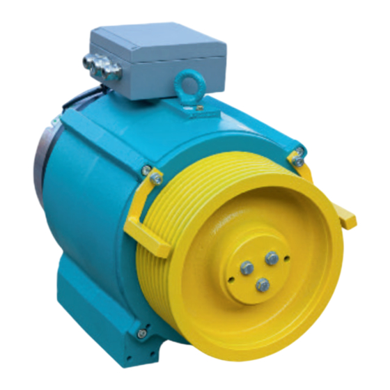
Gearless Lift Machine Code GM.8.003277.EN Date 22.09.2016 WSG-S1.2/3 Version 0.17 Operating Instructions Page 3. Product overview 3.1. Product description The compact gearless WSG-S1 synchronous lift machines are designed for traction sheave lifts. They are distin- guished by their high efficiency, extremely low noise and excellent operating characteristics. The machines can be supplied for several rated speeds, which can be further adapted to meet individual cus- tomer requirements. -
Page 7: Transport And Storage
Gearless Lift Machine Code GM.8.003277.EN Date 22.09.2016 WSG-S1.2/3 Version 0.17 Operating Instructions Page 3.2. Transport and storage • The lift machines leave the factory in perfect condition after being tested. • Make a visual check for any external damage immediately upon their arrival on site. If any damage is found to have occurred in transit, make a notice of claim in the presence of the carrier. -
Page 8: Installation
Gearless Lift Machine Code GM.8.003277.EN Date 22.09.2016 WSG-S1.2/3 Version 0.17 Operating Instructions Page 4. Installation 4.1. Setting up Be sure to use calculations to check the base frame or foundation loads before installing the DANGER lift machine. • The machines can be used in lift systems with or without a machine room •... -
Page 9: Electrical Connection
Gearless Lift Machine Code GM.8.003277.EN Date 22.09.2016 WSG-S1.2/3 Version 0.17 Operating Instructions Page Ambient conditions • The following ambient conditions must be ensured on site Altitud: max. 1,000 m a.s.l. Ambient temperature: -5°C ... 40 °C Max. rel. humidity: 85% at 20°C (no moisture condensation) •... -
Page 10: Motor Connection / Winding Protection
Gearless Lift Machine Code GM.8.003277.EN Date 22.09.2016 WSG-S1.2/3 Version 0.17 Operating Instructions Page 4.2.2. Motor connection / Winding protection • The electrical connection of the motor and the winding sensors is made in the terminal box, by power con- nector or by cable (standard length: 5 m). •... - Page 11 Gearless Lift Machine Code GM.8.003277.EN Date 22.09.2016 WSG-S1.2/3 Version 0.17 Operating Instructions Page U1 / 1 Core marking V1 / 2 shield green/yellow W1 / 3 T1 / 5 / BR1 T2 / 6 / BR2 triplet PTC Ferrules Cable cross-section required: The currents specified under the machine data refer to duty type S3-40%.
-
Page 12: Speed/Position Measuring System
Gearless Lift Machine Code GM.8.003277.EN Date 22.09.2016 WSG-S1.2/3 Version 0.17 Operating Instructions Page 4.2.3. Speed/Position measuring system • The basic version of the lift machines is equipped with an sendix 8.5873 SineCosine encoder from Kübler GmbH. The encoder is connected by cable (length: 10m) with open wire ends (no plug). •... -
Page 13: Brake
Gearless Lift Machine Code GM.8.003277.EN Date 22.09.2016 WSG-S1.2/3 Version 0.17 Operating Instructions Page 4.2.4. Brake • Please refer also to the operating instructions for the brake. • The brakes are supplied with DC voltage by the overexcitation rectifiers, which are supplied separately or in the terminal box. - Page 14 Gearless Lift Machine Code GM.8.003277.EN Date 22.09.2016 WSG-S1.2/3 Version 0.17 Operating Instructions Page Monitoring the brakes • The switching states of the brakes are monitored by means of dust-proof microswitches with gold contacts. Both the n.c. and the n.o. contact connections are available. The microswitches must be evaluated separately for each partial brake to ensure compliance WARNING with the requirements of the type examination.
- Page 15 Gearless Lift Machine Code GM.8.003277.EN Date 22.09.2016 WSG-S1.2/3 Version 0.17 Operating Instructions Page As an option, the electrical connection of the brake made by a 9-pole power connector mounted on the brake. A type B ST A 908 FR11 85 001A 000 connector from "intercontec"...
- Page 16 Gearless Lift Machine Code GM.8.003277.EN Date 22.09.2016 WSG-S1.2/3 Version 0.17 Operating Instructions Page Circuitry suggestion for brake control WSG-S1 Subject to changes without notice ! Subject to changes without notice !
-
Page 17: Commissioning
Gearless Lift Machine Code GM.8.003277.EN Date 22.09.2016 WSG-S1.2/3 Version 0.17 Operating Instructions Page 5. Commissioning The following points should be checked or completed: • Check that all performance and application data specified on the name plate of the machine are consistent with your application. -
Page 18: Operation And Maintenance
Gearless Lift Machine Code GM.8.003277.EN Date 22.09.2016 WSG-S1.2/3 Version 0.17 Operating Instructions Page 6. Operation and maintenance 6.1. General • The regulations concerning operation, maintenance and inspection pursuant to the applicable safety regula- tions for lift construction such as DIN EN 81-20, DIN EN 81-50, LD 2014/33/EU and other relevant regulations are to be strictly observed. -
Page 19: Regreasing The Bearings
Gearless Lift Machine Code GM.8.003277.EN Date 22.09.2016 WSG-S1.2/3 Version 0.17 Operating Instructions Page 6.3. Regreasing the bearings The anti-friction bearings have been provided with a grease filling at the factory that is sufficient for the planned service life of the machine. Under normal operating conditions, regreasing is not required or recom- mended. -
Page 20: Emergency Evacuation
Gearless Lift Machine Code GM.8.003277.EN Date 22.09.2016 WSG-S1.2/3 Version 0.17 Operating Instructions Page 6.5. Emergency evacuation All actions for evacuation in case of emergency have to be done by qualified service DANGER personnel. Manually operated evacuation in case of emergency •... -
Page 21: Testing The Brake System To En 81
Gearless Lift Machine Code GM.8.003277.EN Date 22.09.2016 WSG-S1.2/3 Version 0.17 Operating Instructions Page 6.6. Testing the brake system to EN 81 The brake system should be tested with the car about halfway down the shaft. If any motor short-circuit connections have been made, these should be deactivated so that the brake effect can be tested independently. -
Page 22: Replacing The Measuring System
Gearless Lift Machine Code GM.8.003277.EN Date 22.09.2016 WSG-S1.2/3 Version 0.17 Operating Instructions Page 6.7. Replacing the measuring system The measuring system is only accessible from the rear side of the motor. See the mounting instructions for the Kübler encoder. Disassemble the measuring system only if this is necessary because of a defect. Remember to readjust the offset value after reassembly (see the inverter operating instructions). -
Page 23: Trouble Shooting
Gearless Lift Machine Code GM.8.003277.EN Date 22.09.2016 WSG-S1.2/3 Version 0.17 Operating Instructions Page 6.8. Trouble shooting Fault Possible cause Remedy Motor does not start, operates out of • Motor not connected in proper • Connect motor correctly phase sequence control or develops no torque •... -
Page 24: Type Code
Gearless Lift Machine Code GM.8.003277.EN Date 22.09.2016 WSG-S1.2/3 Version 0.17 Operating Instructions Page 7. Type code Example: 2 4 A G- Z1 Z2 . Z3 - X3 X4 X5 X6 X7 X8 X9 Customer specific identifier S = Synchronmotor G = gearless Z1 Z2: Frame size Z3: Overall length: 2 overall lengths are available;... -
Page 25: Technical Data
Gearless Lift Machine Code GM.8.003277.EN Date 22.09.2016 WSG-S1.2/3 Version 0.17 Operating Instructions Page 8. Technical data Duty type: S3 - 40 % ED Traction sheave: dia. 210 mm, dia. 240 mm or dia. 320 mm Dual-circuit fail-safe brake Traction sheave hard- mind. -
Page 26: Dimension Drawing
Gearless Lift Machine Code GM.8.003277.EN Date 22.09.2016 WSG-S1.2/3 Version 0.17 Operating Instructions Page 9. Dimension drawing WSG- S1.2 S1.3 motor Æ D 160 210 240 320 160 210 240 320 Reference values. Achievable nominal load depends on specific lift system data. 118,5 86,5 91,5... -
Page 27: Accessories
Gearless Lift Machine Code GM.8.003277.EN Date 22.09.2016 WSG-S1.2/3 Version 0.17 Operating Instructions Page 10. Accessories 10.1. Connecting cable for measuring systems recom. recommended Inverter type encoder system measurement system cable E-Pack ECN 413 503 325 021 xx (EnDat / SSI) Arkel ARCODE D-Pack ECN 413... -
Page 28: Cable Set For Motor And Brake
Gearless Lift Machine Code GM.8.003277.EN Date 22.09.2016 WSG-S1.2/3 Version 0.17 Operating Instructions Page 10.2. Cable set for motor and brake motor cable brake cable (magnet) brake cable (monitoring) WSG-Sx xx - cable length [m] 05 - 5 m; 10 - 10 m; 15 - 15 m; Ader / wire motor cable 1 (U1) -
Page 29: Brake Manual Release
Gearless Lift Machine Code GM.8.003277.EN Date 22.09.2016 WSG-S1.2/3 Version 0.17 Operating Instructions Page 10.3. Brake manual release The brake can be fitted with a manual brake Release releasing device on customer request. The device can also be retrofitted. The necessary manual release lever including the Bowden cable for releasing can be delivered, if required. -
Page 30: Rope Guards
Gearless Lift Machine Code GM.8.003277.EN Date 22.09.2016 WSG-S1.2/3 Version 0.17 Operating Instructions Page 10.4. Rope guards The standard version of the WSG-S1 is equipped with the rope slip-off guard (5) (see figure "Machine cross- section" on page 6). In addition, we offer a guard version as shown in the fig- Standard rope slip-off guard ure "Top guard for traction sheave". -
Page 31: Spare Parts
Gearless Lift Machine Code GM.8.003277.EN Date 22.09.2016 WSG-S1.2/3 Version 0.17 Operating Instructions Page 11. Spare parts Item Part Description Motor traction sheave acc. machine nameplate type code X5 X6 X7 Measuring system (depending on spec.) ECN 413 / SSI / 2048 incr. / clamping ring ECN 413 / ENDAT / 2048 Inkr. - Page 40 Annex to the EC Type-Examination Certificate No. EU-BD 863 of 2016-03-18 Scope of application Use as braking device – part of the the protection device against overspeed for the car mov- ing in upwards direction – permissible brake torques and tripping rotary speeds 1.1.1 Permissible brake torque when the braking device acts on the shaft of the traction sheave while the car is moving upward...
- Page 41 Annex to the EC Type-Examination Certificate No. EU-BD 863 of 2016-03-18 Conditions Above mentioned safety component represents only a part at the protection device against over- speed for the car moving in upwards direction and unintended car movement. Only in combination with a detecting and triggering component in accordance with the standard (two separate compo- nents also possible), which must be subjected to an own type-examination, can the system created fulfil the requirements for a protection device.
- Page 42 Enclosure to the EU Type-Examination Certificate No. EU-BD 863 of 2016-03-18 Authorised Manufacturer of Serial Production – Production Sites (valid from: 2016-03-18): Company INTORQ GmbH & Co. KG Address Wülmser Weg 5 31855 Aerzen – Germany Company INTORQ (Shanghai) Co., Ltd. Address No.
- Page 46 setting the standard INTORQ BFK464 Electromagnetically Released Spring-Applied Brake Translation of the Original Operating Instructions www.intorq.com www.intorq.com...
- Page 47 This documentation applies to the: BFK464-17S BFK464-18S BFK464-18S.2 BFK464-19S BFK464-20S BFK464-20S.1 BFK464-22S BFK464-25S BFK464-25S.1 BFK464-28S Product key INTORQ Legend for the product key INTORQ BFK464 Product group Brakes Product type Spring-applied brake Type Size 17, 18, 19, 20, 22, 25, 28 Design Not coded: Supply voltage, hub bore, options INTORQ | BA 14.0197 | 04/2016...
- Page 48 Identification Packaging label Example Manufacturer Type number Type (see product key) Bar code Designation Qty. per box Rated/holding voltage Rated torque Rated/holding power Hub diameter Packaging date Model identification CE mark Note Name plate Example Manufacturer CE mark Type (see product key) EC-type examination identification Rated/holding voltage Rated/holding power...
- Page 49 Document history Material number Version Description 33002149 09/2010 TD09 First edition 33002149 11/2010 TD09 Enlarged to include 19S and 28S sizes Supplement of the tables in the Characteristics chapter Supplement of the important instructions in the Commissioning and operation chapter 33002149 08/2012 TD09 Supplement of the model identification number for the sizes 18S, 19S...
- Page 50 Contents Preface and general information .......................... 6 About these Operating Instructions ......................6 Terminology used ............................6 Conventions in use ............................6 Abbreviations used ............................7 Safety instructions and notices ........................8 Scope of delivery ............................9 Disposal ................................ 9 Drive systems .............................
-
Page 51: Preface And General Information
Preface and general information Preface and general information About these Operating Instructions ❚ These Operating Instructions will help you to work safely with the spring-applied brake with electromag- netic release. They contain safety instructions that must be followed. ❚ All persons working on or with the electromagnetically released spring-applied brakes must have the Op- erating Instructions available and observe the information and notes relevant for them. -
Page 52: Abbreviations Used
Preface and general information Abbreviations used Letter symbol Unit Designation Rated frictional force Current Holding current, at 20 °C and holding voltage Release current, at 20 °C and release voltage Rated current, at 20 °C and rated voltage Tightening torque of fixing screws Braking torque at a constant speed of rotation Rated torque of the brake, rated value at a relative speed of rotation of 100 rpm Maximum occurring speed of rotation during the slipping time t... -
Page 53: Safety Instructions And Notices
Preface and general information Letter symbol Unit Designation Delay during engagement (time from switching off the supply voltage to the beginning of the torque rise) Rise time of the braking torque, time from the start of torque rise until reach- ing the braking torque Over-excitation time Voltage... -
Page 54: Scope Of Delivery
Preface and general information Danger level DANGER DANGER indicates a hazardous situation which, if not avoided, will result in death or serious injury. WARNING WARNING indicates a potentially hazardous situation which, if not avoided, could result in death or serious injury. CAUTION CAUTION indicates a hazardous situation which, if not avoided, could result in minor or mod- erate injury. -
Page 55: Drive Systems
Preface and general information Drive systems Labelling Drive systems and components are unambiguously designated by the indications on the name plate. Manufacturer: INTORQ GmbH & Co. KG, Wülmser Weg 5, D-31855 Aerzen, Germany ❚ The spring-applied INTORQ brake is also delivered in single modules which can then be put together by the customer according to their requirements. -
Page 56: Safety Instructions
Safety instructions Safety instructions General safety instructions ❚ INTORQ components: ... must only be used as directed..must not be commissioned if they are noticeably damaged..must not be technically modified..must not be commissioned if they are incompletely mounted or connected.. -
Page 57: Application As Directed
Safety instructions Application as directed ❚ INTORQ components: ... are intended for use in machinery and systems..must only be used for their intended and confirmed purposes..must only be operated under the ambient conditions prescribed in these Operating Instructions.. -
Page 58: Technical Specifications
Technical specifications Technical specifications Product description Versions Abb. 1 Design of the BFK464- S / S.1 / S.2 spring-applied brake 1.1 Stator Shaft 10 Socket head cap screw, DIN EN ISO 4762 1.2 Pressure springs Flange (optional) 13 Cover plate (optional) Armature plate Coil 16 Microswitch... - Page 59 Technical specifications The division of the brake circuits is done using a two-part armature disk (2) with the respectively allocated compression springs (1.2) and electromagnetic coils (8). Each brake circuit can be operated individually due to the separate supply lines for each coil group and armature disk segment ( 32).
- Page 60 Technical specifications 3.1.5 Manual release (optional) To temporarily release the brake when there is no electricity available, a manual release function is available as an option (instead of the transport safety bolts otherwise used). The manual release system works on both brake circuits together.
-
Page 61: Rated Data
Technical specifications Rated data 3.2.1 Dimensions 1.1 Stator, complete Armature plate Flange Type Stator weight Air gap Perm. wear Rotor thickness complete +0.05 [mm] [mm] [mm] min. [mm] max. [mm] m [kg] Lmax BFK464-17S BFK464-18S 12.7 BFK464-18S.2 14.5 BFK464-19S 18.8 BFK464-20S 15.7 BFK464-20S.1... - Page 62 Technical specifications Pitch Type Fixing screws Minimum thread depth Tightening torque circle DIN 912 +1.0 mm without with without with without with Flange Flange Flange Flange flange flange [mm] Thread [mm] [mm] [mm] [mm] [Nm] [Nm] BFK464-17S 6 x M8x85 6 x M8x95 24.6 BFK464-18S...
-
Page 63: Rating (Design Data)
Technical specifications Rating (design data) Abb. 2 Operating times of the spring-applied brakes Engagement time Reaction delay of engagement Disengagement time (up to M = 0.1 M Rise time of the braking torque Braking torque at a constant speed of rotation Voltage Type Rated... -
Page 64: Switching Energy / Operating Frequency
Technical specifications Disengagement time The disengagement time is not influenced by DC or AC switching operations. Engagement time The transition from brake-torque free state to holding braking torque is not free of time lags. For emergency braking, short engagement times for the brake are absolutely essential. The DC switching in connection with a suitable spark suppressor is therefore to be provided. -
Page 65: Emissions
Technical specifications Emissions Electromagnetic compatibility NOTICE The user must ensure compliance with EMC Directive 2014/30/EU using appropriate controls and switching devices. If an INTORQ rectifier is used for the DC switching of the spring-applied brake and if the operating frequency exceeds five switching operations per minute, the use of a mains filter is required. -
Page 66: Mechanical Installation
Mechanical installation Mechanical installation Important notes NOTICE The toothed hub and screws must not be lubricated with grease or oil. Necessary tools Type Torque wrench Open-jawed spanner Allen key for transport Insert for hexagonal socket (Allen) safety bolts screws Sleeve bolts Manual release - nuts Width across... -
Page 67: Assembly
Mechanical installation Assembly 4.3.1 Important notes Brake size Minimum requirements: Use as counter friction surface Evennes Axial Roughness Others Material run-out [mm] [mm] ❚ Threaded holes with mini- 17 – 28 S235 JR < 0.1 Rz10 mum thread depth ❚ Free of grease and oil EN-GJL-250 Rz16 Tab. -
Page 68: Installation Procedure
Mechanical installation Installation procedure NOTICE The toothed hub and screws must not be lubricated with grease or oil. NOTICE When you have ordered a version with flange, attach the hub first ( 23), then continue with the "Assembly of the counter friction faces". 4.4.1 Install the hub onto the shaft NOTICE... - Page 69 Mechanical installation 4.4.2 Brake assembly Assembly without counter friction face Abb. 5 Assembly without counter friction face 15 End shield Install the counter friction faces Abb. 6 Assembly of the flange Flange 15 End shield 1. Hold the flange (6) to the end shield (15). 2.
- Page 70 Mechanical installation Assembly of the rotor Abb. 7 Mounting the hub onto the shaft Complete rotor Flange 15 End shield 1. Push the complete rotor (3) onto the hub (4) and check whether it can be moved by hand. Do not use any lubricant! (Exception: rotor with toothing that has been sprayed by the manufacturer.) In the following sections, only assembly for the versions with flange will be described.
- Page 71 Mechanical installation 4.4.3 Check the air gap Abb. 9 Checking "s " Air gap, s 1.1 Stator Flange 10 Cylinder head bolt Armature plate Sleeve bolt 15 End shield 1. Check the air gap "s " near the bolts (10) using a feeler gauge and compare the values to the values for "s "...
- Page 72 Mechanical installation 4.4.4 Adjusting the air gap WARNING Danger: rotating parts! Switch off the voltage. The drive system must be free of loads. Abb. 10 1. Loosen the bolts (10). NOTICE First correctly adjust the air gap with every 2nd bolt (10) / sleeve bolt (9)! The other three sleeve bolts should be screwed into the stator so that they do not touch the flange or the bearing shield.
- Page 73 Mechanical installation DANGER Brake may fail If the manual release is not adjusted correctly the brake may fail. Possible consequences: ❚ Severe injuries or material damage. Protective measure: ❚ Ensure that the dimension "s" is observed. 4.4.5 Cover ring assembly NOTICE Brakes without flange require a groove in the bearing shield for the lip of the cover ring.
- Page 74 Mechanical installation 4.4.6 Manual release assembly (optional) NOTICE The assembly of the manual release is done to the spring-applied brake which is already fitted to the bearing shield 24. The air gap of the brake is set to the rated air gap, Abb.
- Page 75 Mechanical installation 4. Screw self-locking nuts (12.8) onto the stud bolts and tighten them until the dimension "s" has been set. NOTICE Before setting the dimension "s", it is imperative that the air gap "s " is checked, and adjusted to "s "...
-
Page 76: Electrical Installation
Electrical installation Electrical installation Electrical connection 5.1.1 Important notes DANGER There is a risk of injury by electrical shock! ❚ The electrical connections must only be made by skilled personnel! ❚ Only carry out connection work when no voltage is applied (no live parts)! There is a risk of unintended start-ups or electric shock. -
Page 77: Bridge/Half-Wave Rectifier (Optional)
Electrical installation 5.1.2 Switching suggestions 230 V AC or 400 V AC Brake circuit 1 Brake circuit 2 observe the observe the polarity polarity Suppressor Suppressor circuit circuit Brake Brake Abb. 14 INTORQ BFK464 connection diagram Switching on ❚ K2/K4 must be switched on before or at the same time as K1/K3! Switching off ❚... - Page 78 Electrical installation 5.2.1 Assignment: Bridge/half-wave rectifier – brake size Rectifier type Supply voltage Coil voltage Assigned brake Release / holding [V AC] [V DC] BFK464-17S BFK464-18S BFK464-18S.2 BFK464-19S BFK464-20S BEG-561-255-130 ±10% 205 / 103 BFK464-20S.1 BFK464-22S BFK464-25S BFK464-25S.1 BFK464-28S BFK464-17S BFK464-18S BFK464-18S.2 BFK464-19S...
- Page 79 Electrical installation Dimensions Fastening options Abb. 15 Dimensions and possible installations of bridge/half-wave rectifier 5.2.2 Technical specifications Rectifier type Bridge / half-wave rectifier Output voltage for bridge rectification 0.9 x U Output voltage for half-wave rectification 0.45 x U Ambient temperature (storage/operation) [°C] -25 –...
-
Page 80: Electrical Connection
Electrical installation 5.2.3 Permissible current load at ambient temperature 1 For screw assembly with metal surface (good heat dissipation) 2 For other assembly (e.g. adhesive) Electrical connection DANGER There is a risk of injury by electrical shock! The brake must only be electrically connected when no voltage is applied! NOTICE Compare the coil voltage of the stator to the DC voltage of the installed rectifier. -
Page 81: Commissioning And Operation
Commissioning and operation Commissioning and operation Important notes DANGER ❚ The live connections and the rotating rotor must not be touched. ❚ The drive must not be running when checking the brake. ❚ The brakes are dimensioned in such a way that the given rated torques are reached safely after a short run-in process. - Page 82 Commissioning and operation 1. The switching contact for the brake must be open. 2. Remove two bridges from the motor terminals to de-energise the motor. Do not disconnect the supply voltage for the brake. Apply DC voltage to the brake. NOTICE If the brake is connected to the neutral point of the motor, the PE conductor must also be con- nected to this point.
-
Page 83: Commissioning
Commissioning and operation 6.2.2 Test that the manual release functions NOTICE ❚ The manual release is designed for activation via a Bowden cable. ❚ Releasing an individual brake circuit is only possible electrically. DANGER Danger: rotating parts! The drive system must be free of loads. The motor must not run! Abb. -
Page 84: During Operation
Commissioning and operation During operation DANGER Danger: rotating parts! The running rotor must not be touched. DANGER There is a risk of injury by electrical shock! Live connections must not be touched. ❚ Checks must be carried out regularly. Pay special attention to: unusual noises or temperatures loose fixing elements the condition of the electrical cables... -
Page 85: Maintenance And Repair
Maintenance and repair Maintenance and repair Wear of spring-applied brakes INTORQ spring-applied brakes are wear-resistant and designed for long maintenance intervals. The friction lining and braking mechanism are subject to operational wear. For safe and trouble-free operation, the brake must be checked at regular intervals or replaced, if necessary NOTICE Braking torque reduction The air gap must not be re-adjusted after it has been correctly adjusted during the initial... -
Page 86: Inspections
Maintenance and repair Inspections To ensure safe and trouble-free operations, the spring-applied brakes must be checked at regular intervals and, if necessary, replaced. Servicing will be easier at the plant if the brakes are made accessible. This must be considered when installing the drives in the plant. Primarily, the required maintenance intervals for industrial brakes result from their load during operation. -
Page 87: Maintenance
Maintenance and repair Maintenance NOTICE Brakes with defective armature plates, socket head cap screws, springs or counter friction faces must always be replaced completely. Generally observe the following for inspections and maintenance works: ❚ Contamination by oils and greases should be removed using brake cleaner, or the brake should be replaced after determining the cause. - Page 88 Maintenance and repair 7.3.3 Release / voltage 1. Start motor and control system! DANGER Danger: rotating parts! The running rotor must not be touched. DANGER There is a risk of injury by electrical shock! Live connections must not be touched. 2.
-
Page 89: Spare-Parts List
Maintenance and repair Spare-parts list ❚ Only parts with item numbers are available. The item numbers are only valid for the standard design. ❚ Please include the following information with the order: Order number of the brake Position number of the spare part Abb. -
Page 90: Ordering Spare Parts
Maintenance and repair Ordering spare parts INTORQ BFK464- S / S.1 / S.2, stator, complete Size Design 103 V / 51.5 V Voltage 103 V / 72 V 205 V / 103 V 360 V / 180 V ________ Nm Braking torque Standard (600 mm) Cable length... -
Page 91: Troubleshooting And Fault Elimination
Troubleshooting and fault elimination Troubleshooting and fault elimination If any malfunctions should occur when operating the braking system, please check for possible causes based on the following table. If the fault cannot be fixed or eliminated by one of the listed measures, please contact customer service. - Page 92 Troubleshooting and fault elimination Fault Cause Remedy Brake does not release Microswitch incorrectly wired Check the wiring of the microswitch and correct it. Microswitch incorrectly set Replace the complete stator and make a complaint about the setting of the microswitch to the manufacturer. Air gap too big Adjust the air gap ( Measure the rotor thickness and compare against the min-...
- Page 93 Notes Notes INTORQ | BA 14.0197 | 04/2016...
- Page 94 INTORQ GmbH & Co KG Germany PO Box 1103 D-31849 Aerzen Wülmser Weg 5 D-31855 Aerzen +49 5154 70534-444 +49 5154 70534-200 info@intorq.com INTORQ (Shanghai) Co., Ltd. No. 600, Xin Yuan Nan Road, Building No. 6 / Zone B Nicheng town, Pudong 201306 Shanghai ...
Need help?
Do you have a question about the servogearless WSG-S1.2 and is the answer not in the manual?
Questions and answers