Table of Contents
Advertisement
Quick Links
Gearless Lift Machine
WSG-S2.3
Operating Instructions
Reprinting, translation or reproduction in any form -
whether in part or in full - requires the prior written per-
mission of WITTUR Holding GmbH.
Änderungen vorbehalten!
Gearless Lift Machines
servogearless
WSG-S2.3
WITTUR Holding GmbH
Rohrbachstraße 26-30 • D-85259 Wiedenzhausen, Germany
Tel. +49 (0) 81 34/18-0 • Fax +49 (0) 81 34/18-49
http://www.wittur.com, E-mail: info@wittur.com
Seite/page
Datum/date
Stand/version
eco
Wittur Holding GmbH reserves the right to make
changes in the information and pictures contained in
these operating instructions without prior notice.
Subject to changes without notice!
1
08.10.2013
0.8
Advertisement
Chapters
Table of Contents

Related Manuals for WITTUR servogearless WSG-S2.3


Summary of Contents for WITTUR servogearless WSG-S2.3
- Page 1 Tel. +49 (0) 81 34/18-0 • Fax +49 (0) 81 34/18-49 http://www.wittur.com, E-mail: info@wittur.com Reprinting, translation or reproduction in any form - Wittur Holding GmbH reserves the right to make whether in part or in full - requires the prior written per- changes in the information and pictures contained in mission of WITTUR Holding GmbH.
- Page 2 These operating instructions are applicable to lift machines: WSG - S2.3..WITTUR Electric Drives GmbH reserves the right to correct or change the contents of this manual and these product details without prior notice. We expressly reserve the right to make technical changes which improve the lift machines or their safety standards without prior notice.
-
Page 3: Table Of Contents
Gearless Lift Machine Seite/page Datum/date 08.10.2013 WSG-S2.3 Stand/version Operating Instructions Contents 1. General information ..........................4 1.1. About this operating manual ............4 1.2. -
Page 4: General Information
Gearless Lift Machine Seite/page Datum/date 08.10.2013 WSG-S2.3 Stand/version Operating Instructions General information 1.1. About this operating manual The purpose of this operating manual is to ensure that any work on WSG-S2 lift machines is carried out safely. Please regard it as part of the product and keep it within easy reach. All persons working on or with WSG-S2 lift machines must have read and understood this operating manual. -
Page 5: Format Of The Safety Instructions
Gearless Lift Machine Seite/page Datum/date 08.10.2013 WSG-S2.3 Stand/version Operating Instructions Qualified personnel Only qualified personnel are authorised to perform any planning, installation or maintenance work, and this must be done in accordance with the relevant instructions. The personnel must be trained for the job and must be familiar with the installation, assembly, commissioning and operation of the product. -
Page 6: Product Description
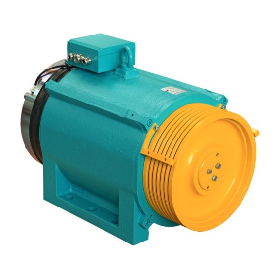
Gearless Lift Machine Seite/page Datum/date 08.10.2013 WSG-S2.3 Stand/version Operating Instructions Product description The compact gearless WSG-S2 synchronous lift machines are designed for traction sheave lifts. They are distin- guished by their high efficiency, extremely low noise and excellent operating characteristics. The machines can be supplied for several rated speeds, which can be further adapted to meet individual cus- tomer requirements. -
Page 7: Transport And Storage
Gearless Lift Machine Seite/page Datum/date 08.10.2013 WSG-S2.3 Stand/version Operating Instructions Transport and storage • The lift machines leave the factory in perfect condition after being tested. • Make a visual check for any external damage immediately upon their arrival on site. If any damage is found to have occurred in transit, make a notice of claim in the presence of the carrier. -
Page 8: Installation
Gearless Lift Machine Seite/page Datum/date 08.10.2013 WSG-S2.3 Stand/version Operating Instructions Installation 5.1. Setting up Be sure to use calculations to check the base frame or foundation loads before installing the DANGER lift machine. • The machines can be used in lift systems with or without a machine room. •... -
Page 9: Electrical Connection
Gearless Lift Machine Seite/page Datum/date 08.10.2013 WSG-S2.3 Stand/version Operating Instructions Securing the machine • The rope force can be applied to the lift machine in any direction. • The machine should be mounted on rubber pads for vibration damping. • Fasten the machine using bolts - 4 x M 24 bolts (strength class 8.8;... -
Page 10: Motor Connection / Winding Protection
Gearless Lift Machine Seite/page Datum/date 08.10.2013 WSG-S2.3 Stand/version Operating Instructions 5.2.2. Motor connection / Winding protection • The electrical connection of the motor, the brake and the winding sensors is made in the terminal box locat- ed on the motor. •... - Page 11 Gearless Lift Machine Seite/page Datum/date 08.10.2013 WSG-S2.3 Stand/version Operating Instructions Cable cross-section required: The currents specified under the machine data refer to duty type S3-40%. This must be taken into account when selecting the cable cross-section required. The continuous r.m.s. value required for the selected cable is approximated Permissible max.
-
Page 12: Speed/Position Measuring System
Gearless Lift Machine Seite/page Datum/date 08.10.2013 WSG-S2.3 Stand/version Operating Instructions 5.2.3. Speed/Position measuring system • The basic version of the lift machines is equipped with an ECN 413 SineCosine encoder from Heidenhain GmbH. The encoder is connected via a 17-pole signal plug connector fitted to the measuring system housing. •... -
Page 13: Brake
Gearless Lift Machine Seite/page Datum/date 08.10.2013 WSG-S2.3 Stand/version Operating Instructions 5.2.4. Brake • Please refer also to the operating instructions for the brake. • The brakes are supplied with DC voltage by the overexcitation rectifiers, which are supplied separately or in the terminal box. - Page 14 Gearless Lift Machine Seite/page Datum/date 08.10.2013 WSG-S2.3 Stand/version Operating Instructions Monitoring the brakes • The switching states of the brakes are monitored by means of dust-proof microswitches with gold contacts. Both the n.c. and the n.o. contact connections are available. The microswitches must be evaluated separately for each partial brake to ensure compliance WARNING with the requirements of the type examination.
- Page 15 Gearless Lift Machine Seite/page Datum/date 08.10.2013 WSG-S2.3 Stand/version Operating Instructions Circuitry suggestion for brake control WSG-S2.3 Änderungen vorbehalten! Subject to changes without notice!
-
Page 16: Commissioning
Gearless Lift Machine Seite/page Datum/date 08.10.2013 WSG-S2.3 Stand/version Operating Instructions Commissioning The following points should be checked or completed: • Remove all securing, auxiliary and installation tools from the danger area. • Check that the lift machine is used for its intended purpose and that the permissible ambient conditions are met. -
Page 17: Operation And Maintenance
Gearless Lift Machine Seite/page Datum/date 08.10.2013 WSG-S2.3 Stand/version Operating Instructions Operation and maintenance 7.1. General • The regulations concerning operation, maintenance and inspection pursuant to the applicable safety regulations for lift construction such as DIN EN 81 "Safety rules for the construction and installation of lifts", Part 1: "Electric lifts", and other relevant regulations are to be strictly observed. -
Page 18: Regreasing The Bearings
Gearless Lift Machine Seite/page Datum/date 08.10.2013 WSG-S2.3 Stand/version Operating Instructions 7.3. Regreasing the bearings The anti-friction bearings have been provided with a grease filling at the factory that is sufficient for the planned service life of the machine. Under normal operating conditions, regreasing is not required or recommended. -
Page 19: Emergency Evacuation
Gearless Lift Machine Seite/page Datum/date 08.10.2013 WSG-S2.3 Stand/version Operating Instructions 7.5. Emergency evacuation • The lift design engineer must always provide an electric return motion control or a manual rewinder (please note EN 81-1 / 12.5.2). • Should a failure occur with the car at rest, the car can be moved with the drive connected to the mains or, in the case of mains failure, to an uninterruptible power supply (UPS), or mechanically under its own load with the emergency brakes temporarily released. -
Page 20: Replacing The Measuring System
Gearless Lift Machine Seite/page Datum/date 08.10.2013 WSG-S2.3 Stand/version Operating Instructions 7.7. Replacing the measuring system The measuring system is only accessible from the rear side of the motor. See the mounting instructions for the Heidenhain encoder. Disassemble the measuring system only if this is necessary because of a defect. Remember to readjust the offset value after reassembly (see the converter operating instructions). -
Page 21: Trouble Shooting
Gearless Lift Machine Seite/page Datum/date 08.10.2013 WSG-S2.3 Stand/version Operating Instructions 7.8. Trouble shooting Fault Possible cause Remedy Motor does not start, operates out of • Motor not connected in proper • Connect motor correctly phase sequence control or develops no torque •... -
Page 22: Type Code
Gearless Lift Machine Seite/page Datum/date 08.10.2013 WSG-S2.3 Stand/version Operating Instructions Type code Example: G- S2 . 3 2 A G- S2 . 3 - X3 X4 X5 X6 X7 X8 X9 Customer specific identifier S = Synchronous motor G = gearless Frame size Overall length X1: Customer specific identifier... - Page 23 Gearless Lift Machine Seite/page Datum/date 08.10.2013 WSG-S2.3 Stand/version Operating Instructions Änderungen vorbehalten! Subject to changes without notice!
-
Page 24: Technical Data
Gearless Lift Machine Seite/page Datum/date 08.10.2013 WSG-S2.3 Stand/version Operating Instructions Technical data Duty type: S3 - 40 % ED Dual-circuit fail-safe brake Traction sheave: dia. 320 mm or dia. 400 mm Traction sheave hard- mind. 220 HB 30 Type: BFK 464-28 nesse: formbeständige Keilrille HRC 55 Max. -
Page 25: Dimension Drawing
Gearless Lift Machine Seite/page Datum/date 08.10.2013 WSG-S2.3 Stand/version Operating Instructions 10. Dimension drawing Ø 6 Befestigungsbohrungen und 4 Gewindebohrungen M 24 Ø 6 mounting holes and 4 threaded holes M 24 WSG- S2.3 Æ D Motor / motor [kg] Masse / weight Trägheitsmoment [kgm inertia... -
Page 26: Accessories
Gearless Lift Machine Seite/page Datum/date 08.10.2013 WSG-S2.3 Stand/version Operating Instructions 11. Accessories 11.1. Connecting cable for measuring systems recom. recommended Inverter type encoder system measurement system cable ARKEL ADrive ECN 413 502 452 021 xx (EnDat or SSI) CT unidrive SP emotron/ ECN 413 Dietz... -
Page 27: Cable Set For Motor And Brake
Gearless Lift Machine Seite/page Datum/date 08.10.2013 WSG-S2.3 Stand/version Operating Instructions 11.2. Cable set for motor and brake Motorkabel / motor cable 503 458 A21-xx Bremsenkabel (Magnet) Brake cable (magnet) 503 459-xx-1 Bremsenkabel (Überwachung) 503 459-xx-2 Brake cable (monitoring) A = 1: 1,5mm <... -
Page 28: Brake Manual Release
Gearless Lift Machine Seite/page Datum/date 08.10.2013 WSG-S2.3 Stand/version Operating Instructions 11.3. Brake manual release The brake can be fitted with Alternatively, another simple version of the manual a manual brake releasing releasing device is available for lifts with a machine device on customer request. -
Page 29: Rope Guards
Gearless Lift Machine Seite/page Datum/date 08.10.2013 WSG-S2.3 Stand/version Operating Instructions 11.4. Rope guards The standard version of the WSG-S1/S2 is equipped with the rope slip-off guard (5) (see figure "Machine cross- section" on page 7). Alternatively a version „multi roof“ is availible. Standard rope slip-off guard only for = 320 mm... -
Page 30: Spare Parts
Gearless Lift Machine Seite/page Datum/date 08.10.2013 WSG-S2.3 Stand/version Operating Instructions 12. Spare parts Item Teil Bezeichnung Motor traction sheave acc. machine nameplate type code X5 X6 X7 Measuring system (depending on spec.) ECN 413 / SSI / 2048 incr. / clamping ring ECN 413 / ENDAT / 2048 Inkr. - Page 43 INTORQ BFK464−18S; 19S; 20S; 25S und 28S INTORQ BFK464−20S.1 Electromagnetically released spring−applied brake Operating Instructions setting the standard www.intorq.de...
- Page 44 j | BA 14.0197 | 11/2010 This documentation applies to ... BFK464−18S BFK464−19S BFK464−20S BFK464−20S.1 BFK464−25S BFK464−28S BFK464−XX−S−011a.iso/dms BFK464−XX−S−011.iso/dms Product key Product key INTORQ − Legend for INTORQ BFK464−XXS/S.1 product key Product group Brakes Product family Spring−applied brake Type Size 18, 19, 20, 25, 28 Design Not coded: supply voltage, hub bore, options...
- Page 45 j | BA 14.0197 | 11/2010 Identification Package label Example Manufacturer Bar code Type (see product key) Type No. Name Quantity per box Rated/holding voltage Rated torque Packing date Rated/holding power Hub diameter Model identification Additional information CE designation BFK464−XX−S−013.iso/dms Nameplate Example Manufacturer...
- Page 46 j | BA 14.0197 | 11/2010 Contents Preface and general information ........About these Operating Instructions .
- Page 47 j | BA 14.0197 | 11/2010 Contents Spare−parts list ..........Spare parts order .
-
Page 48: Preface And General Information
j | BA 14.0197 | 11/2010 Preface and general information Preface and general information About these Operating Instructions These Operating Instructions will help you to work safely on and with the spring−applied brake with electromagnetic release. They contain safety instructions that must be followed. -
Page 49: Abbreviations Used
j | BA 14.0197 | 11/2010 Preface and general information Abbreviations used Abbreviation Unit Designation [kW] Electrical power at 20°C [Nm] Tightening torque [ms] Engagement time, t [ms] Disengagement time (time from the beginning of the torque drop to reaching 0.1 M [ms] Delay during engagement (time from switching off the supply voltage to the beginning of the torque rise) -
Page 50: Drive Systems
j | BA 14.0197 | 11/2010 Preface and general information Drive systems 1.7.1 Labelling Drive systems and components are unambiguously designated by the indications on the nameplate. Manufacturer: INTORQ GmbH & Co KG, Wülmser Weg 5, D−31855 Aerzen The spring−applied INTORQ brake is also delivered in single modules and individually combined to its modular design. -
Page 51: Safety Instructions
j | BA 14.0197 | 11/2010 Safety instructions Safety instructions General safety information INTORQ components ... – ... must only be applied as directed. – ... must not be commissioned if they are noticeably damaged. – ... must not be technically modified. –... -
Page 52: Application As Directed
j | BA 14.0197 | 11/2010 Safety instructions Application as directed INTORQ components ... – ... are intended for use in machinery and systems. – ... must only be used for the purposes ordered and confirmed. – ... must only be operated under the ambient conditions prescribed in these Operating Instructions. -
Page 53: Notes Used
j | BA 14.0197 | 11/2010 Safety instructions Notes used The following pictographs and signal words are used in this documentation to indicate dangers and important information: Safety instructions Structure of safety instructions: Danger! Characterises the type and severity of danger Note Describes the danger Possible consequences:... -
Page 54: Technical Data
j | BA 14.0197 | 11/2010 Technical data Technical data Product description Versions BFK464−XX−S−002.iso/dms Fig. 1 Aufbau einer Federkraftbremse BFK464−LLS / S.1 Stator Shaft Cheese head screws Compression springs Flange (optional) Cover seal (optional) Armature plate Coil Microswitch Complete rotor Sleeve bolts Noise reducer (optional) - Page 55 j | BA 14.0197 | 11/2010 Technical data 3.1.1 General information The spring−applied brake is designed for the conversion of mechanical work and kinetic energy into heat. For operating speed, see ^ 15 Rated data. Due to the static brake torque, the brake can hold loads without speed difference.
- Page 56 j | BA 14.0197 | 11/2010 Technical data 3.1.3 Brake release In braked state, there is an air gap "s " between the stator (1.1) and the armature plate Lü segments (2). To release the brake, the coils (8) of the two magnetic circuits are excited with the DC voltage provided.
-
Page 57: Rated Data
j | BA 14.0197 | 11/2010 Technical data 3.1.7 Noise reduction (optional) In addition to the standard noise reduction, the armature plates can be equipped with noise reducers. Thus, switching noises will be reduced. Rated data 3.2.1 Dimensions BFK464−XX−S−004−a.iso/dms Type Air gap Perm. - Page 58 j | BA 14.0197 | 11/2010 Technical data Type Pitch circle Fixing screws DIN 912 Minimum thread depth Tightening torque +1.0 mm ohne Flansch mit Flansch ohne mit Flansch ohne mit Flansch Flansch Flansch Æ[mm] Gewinde [mm] [mm] [mm] [mm] [Nm] [Nm] BFK464−18S...
-
Page 59: Rated Data (Selection Data)
j | BA 14.0197 | 11/2010 Technical data Rated data (selection data) BFKXXX−011.iso/dms Fig. 2 Operating times of the spring−applied brakes Engagement time Reaction delay during engagement Disengagement time (up to M = 0.1 M Rise time of the brake torque Brake torque Excitation rated... -
Page 60: Operating Frequency / Friction Work
j | BA 14.0197 | 11/2010 Technical data Engagement time Short brake engagement times are vital for emergency braking. DC switching together with a suitable spark suppressor must therefore be provided. If the drive system includes a frequency inverter so that the brake is deenergised only when the motor is at standstill, switching on the AC side is also possible (not valid for emergency braking). -
Page 61: Emission
j | BA 14.0197 | 11/2010 Technical data Emission Electromagnetic compatibility Note! The user must ensure compliance with EMC Directive 2004/108/EC using appropriate controls and switching devices. If an INTORQ rectifier is used for the DC switching of an INTORQ spring−applied brake and if the operating frequency exceeds five switching operations per minute, the use of a mains filter is required. -
Page 62: Mechanical Installation
j | BA 14.0197 | 11/2010 Mechanical installation Mechanical installation Important notes Stop! Toothed hub and screws must not be lubricated with grease or oil! Necessary tools Type Torque wrench Open−jawed spanner Allen key for transport safety Insert for hexagon socket screws bolts Sleeve bolts Manual release −... -
Page 63: Mounting
j | BA 14.0197 | 11/2010 Mechanical installation Mounting 4.3.1 Important notes Minimum requirements of the end shield: Material S235 JR , C15 or EN−GJL−250 – If different materials are used, contact INTORQ. Evenness – < 0.1 mm Axial runout 0.10 mm, Roughness Rz 10 to Rz 16 The threaded holes must have the minimum thread depth, dimensions ^ 15. -
Page 64: Installation
j | BA 14.0197 | 11/2010 Mechanical installation 4.3.3 Overview without separate counter friction face with flange (optional) BFK464−XX−S−004.iso/dms BFK464−XX−S−004.iso/dms Installation Stop! Toothed hub and screws must not be lubricated with grease or oil! Note! When you have ordered a version with flange, attach the hub first (^ 23), then continue with the "Assembly of the counter friction faces". - Page 65 j | BA 14.0197 | 11/2010 Mechanical installation 4.4.1 Installation of the hub onto the shaft BFK464−XX−S−005.iso/dms Fig. 4 Installation of the hub onto the shaft Circlip Keyway End shield 1. Insert keyway (4.1) into the shaft. 2. Press hub (4) onto the shaft. 3.
- Page 66 j | BA 14.0197 | 11/2010 Mechanical installation Assembly of the counter friction faces Flange (optional) BFK464−XX−S−007.iso/dms Fig. 6 Assembly of the flange Flange 15 End shield 1. Hold the flange (6) to the end shield (15). 2. Align the through holes in the flange and the threads of the fastening bore holes. Assembly of the rotor BFK464−S−008.iso/dms Fig.
- Page 67 j | BA 14.0197 | 11/2010 Mechanical installation Assembly of the complete stator BFK46420_1−012.iso Fig. 8 Assembly of the complete stator Complete stator End shield Flange Transport safety bolts Allen screw 1. Push the complete stator (1) onto the shaft. –...
- Page 68 j | BA 14.0197 | 11/2010 Mechanical installation 4.4.3 Check air gap BFK46420_1_008.iso/dms Fig. 9 Checking "s " Lü 1.1 Stator Flange Cheese head screw Armature plate Sleeve bolt End shield 1. Check the air gap "s " near the screws (10) using a feeler gauge and compare the Lü...
- Page 69 j | BA 14.0197 | 11/2010 Mechanical installation 1. Unbolt screws (10). Note! Correctly adjust the air gap using every 2nd screw (10) / sleeve bolt (9)! Turn the remaining three sleeve bolts just far enough into the stator to make sure that they do not touch the flange or the end shield.
- Page 70 j | BA 14.0197 | 11/2010 Mechanical installation 4.4.5 Assembly of the cover seal Stop! Brakes without flange require a groove at the end shield for the lip of the cover seal. BFK46420_1−004.iso/dms BFK464−XX−S−002.iso/dms Fig. 11 Assembly of the cover seal Complete stator Flange Cover seal...
- Page 71 j | BA 14.0197 | 11/2010 Mechanical installation 4.4.6 Assembly of the manual release (optional) Note! The manual release is installed when the spring−applied brake has been mounted onto the end shield (see chapters 4.3.1 ... 4.3.4). The air gap of the brake is adjusted to the rated air gap.
- Page 72 j | BA 14.0197 | 11/2010 Mechanical installation Stop! Before adjusting dimensions "s", check air gap "s " and, if necessary, adjust to Lü "s " (^ 15) (^ 23). During air gap adjustment, the brake is not Lürated energised. BFK464−XX−S−004a.iso/dms BFK464−XX−S−015.iso/dms Fig.
-
Page 73: Electrical Installation
j | BA 14.0197 | 11/2010 Electrical installation Electrical installation Electrical connection 5.1.1 Important notes Danger! | Perform electrical connection only when no voltage is applied. | If an "emergency stop" is carried out without the protective circuit provided, the control device may be destroyed. Observe the correct polarity of the protective circuit! Stop! | For checking the individual braking circuits, it must be possible to switch off... -
Page 74: Bridge/Half−Wave Rectifiers (Option)
j | BA 14.0197 | 11/2010 Electrical installation 5.1.2 Circuit proposals BFK464XX_1−006.iso Fig. 14 INTORQ BFK464 connection diagram Switch−on K2/K4 must be switched before or at the same time as K1/K3! Switch−off Normal − AC switching – K2/K4 remain closed –... - Page 75 j | BA 14.0197 | 11/2010 Electrical installation 5.2.1 Assignment: Bridge/half−wave rectifier − brake size Rectifier type AC voltage Coil voltage Assigned brake release/holding [V AC] [V DC] BEG−561−255−030 BFK464−18S BEG−561−255−030 BFK464−19S BEG−561−255−030 BFK464−20S ±10% 205 / 103 BEG−561−255−030 BFK464−20S.1 BEG−561−255−130 BFK464−25S BEG−561−255−130...
-
Page 76: Electrical Connection
j | BA 14.0197 | 11/2010 Electrical installation ( ±20%) Type Input voltage U Max. current I Overexcitation time t max. (40 Hz ... 60 Hz) min. rated max. bridge half−wave with U with U with U 1 min [V ~ ] [V ~ ] [V ~ ] rated... -
Page 77: Commissioning And Operation
j | BA 14.0197 | 11/2010 Commissioning and operation Commissioning and operation Important notes Danger! The live connections and the rotating rotor must not be touched. The drive must not be running when checking the brake. The brakes are designed such that the specified rated torques (^ Tab. 3) will usually be safely reached after a short run−in process. -
Page 78: Function Checks Before Commissioning
j | BA 14.0197 | 11/2010 Commissioning and operation Function checks before commissioning 6.2.1 Operational check Brake with microswitch Danger! The brake must be free of residual torque. The motor must not rotate. Danger! Live connections must not be touched. 1. - Page 79 j | BA 14.0197 | 11/2010 Commissioning and operation Contact type Connection Brake released Microswitch closed NC contact black / grey NO contact black / blue Tab. 5 Switching status of microswitch 6.2.2 Checking the manual release function Note! | The manual release is designed for operation using a Bowden cable. | The braking circuits can only be released electrically.
-
Page 80: Commissioning
j | BA 14.0197 | 11/2010 Commissioning and operation Commissioning 1. Switch on drive system. 2. Carry out a braking test. During operation Danger! The running rotor must not be touched. Danger! Live connections must not be touched. Check the brake regularly during operation. Take special care of: –... -
Page 81: Maintenance/Repair
j | BA 14.0197 | 11/2010 Maintenance/repair Maintenance/repair Wear of spring−applied brakes INTORQ spring−applied brakes are wear−resistant and designed for long maintenance intervals. The friction lining and the mechanical brake components are subject to function−related wear. For safe and trouble−free operation, the brake must be checked and readjusted at regular intervals, and, if necessary, be replaced. -
Page 82: Inspections
j | BA 14.0197 | 11/2010 Maintenance/repair Inspections To ensure safe and trouble−free operation, spring−applied brakes must be checked and maintained at regular intervals. Servicing can be made easier if good accessability of the brakes is provided in the plant. This must be considered when installing the drives in the plant. Primarily, the necessary maintenance intervals for industrial brakes result from the load during operation. -
Page 83: Maintenance
j | BA 14.0197 | 11/2010 Maintenance/repair Maintenance Note! Brakes with defective armature plates, cheese head screws, springs or flanges must be replaced completely. Please observe the following for inspections and maintenance operations: | Remove impurities through oil and grease using brake cleaning agents, if necessary, replace brake after finding out the cause of the contamination. - Page 84 j | BA 14.0197 | 11/2010 Maintenance/repair 7.3.3 Release / voltage 1. Start motor and control system! Danger! The running rotor must not be touched. Danger! Live connections must not be touched. 2. Observe air gap "s " during operation of the drive. The air gap must be zero. Lü...
-
Page 85: Maintenance Operations
j | BA 14.0197 | 11/2010 Maintenance/repair Maintenance operations 7.4.1 Rotor replacement Danger! Disconnect voltage. The brake must be free of residual torque. 1. Switch off voltage! 2. Disconnect the supply cable. 3. Loosen the screws evenly and remove them completely. 4. - Page 86 j | BA 14.0197 | 11/2010 Maintenance/repair Spare−parts list Only parts with item numbers are available. The item numbers are only valid for the standard design. Bore diameter in mm Standard keyway to DIN 6885/1 P9 BFK464−XX−S−010.iso/dms Fig. 17 Spring−applied brake BFK464−LL S / S.1 Item Designation Variant...
- Page 87 j | BA 14.0197 | 11/2010 Maintenance/repair Spare parts order INTORQ BFK464−LLS /S.1, complete stator \ 18 \ 19 \ 20 \ 25 \ 28 Size \ S.1 Design \ 205 V / 103 V Voltage \ 360 V / 180 V ___________Nm Brake torque \ Standard (600 mm)
- Page 88 j | BA 14.0197 | 11/2010 Troubleshooting and fault elimination Troubleshooting and fault elimination If any malfunctions should occur during operation of the drive system, please check the possible causes using the following table. If the fault cannot be eliminated by one of the listed measures, please contact the aftersales service.
- Page 89 j | BA 14.0197 | 11/2010 Troubleshooting and fault elimination Fault Cause Remedy Rotor not thick enough Rotor has not been replaced in time Replace rotor (^ 43) Voltage is not zero during functional Incorrect wiring of microswitch Check and correct the microswitch wiring. test (chapter 6.2) Defective microswitch or incorrect Replace the entire stator and send the defective...
- Page 90 F INTORQ GmbH & Co KG Wülmser Weg 5 D−31855 Aerzen Germany ( +49 (0) 51 54 95 39−01 Ê +49 (0) 51 54 95 39−10 š info@intorq.com ü www.intorq.de Service ( 00 80 00 24 4 68 77 (24 h helpline) Ê...
Need help?
Do you have a question about the servogearless WSG-S2.3 and is the answer not in the manual?
Questions and answers