
Related Manuals for Korenix JetNet 3212G-2C2F


Summary of Contents for Korenix JetNet 3212G-2C2F
- Page 1 Korenix JetNet 3212G-2C2F Industrial 12-port Ethernet Switch User’s Manual Version: 1.0 Date: Dec, 2019 www.korenix.com...
- Page 2 Declaration of CE This product has passed the CE certification for environmental specifications. Test conditions for passing included the equipment being operated within an industrial enclosure. In order to protect the product from being damaged by ESD (Electrostatic Discharge) and EMI leakage, we strongly recommend the use of CE-compliant industrial enclosure products.
-
Page 3: Table Of Contents
Index Index ..................3 1. Introduction ................1 1-1. Features 1-2. Package Checklist ............2 2. Hardware Description ............3 2-1. Dimensions ..............3 2-2. Front Panel ..............4 2-3. Bottom View ..............5 2-4. Wiring the DC Power Inputs .......... 6 2-5. -
Page 4: Introduction
Fault Alarm The JetNet 3212G-2C2F provides an alarm relay to trigger out a real alarm signal for power event. The alarm mechanism can be trigger an external alarm equipment to inform maintenance I.T. engineers. It makes a result of... -
Page 5: Features
Dual DC Power input 10~60V -40~75℃ Hazardous Operating Temperature 1-2. Package Checklist JetNet 3212G-2C2F package includes the following items: JetNet 3212G-2C2F x1 One DIN-Rail clip (already screwed on the back of the product) One Quick Installation Guide... -
Page 6: Index Index
2. Hardware Description 2-1. Dimensions The dimension of JetNet 3212G-2C2F is 135 mm(H) x 74 mm (W) x132 mm (D) ( without DIN rail clip) -
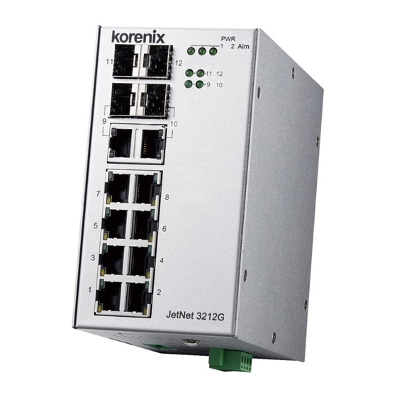
Page 7: Front Panel
2-2. Front Panel The Front Panel of the JetCon 3212G-2C2F is shown in below Power LED Alarm Relay indicator SFP for Link/Activity RJ-45 for Link/Activity Gigabit RJ-45 for 1000 Mbps... -
Page 8: Bottom View
2-3. Bottom View The bottom side of the JetNet 3212G-2C2F includes two 4-pin removable terminal block connectors Earth Ground Screw Terminal Block with screws Power Alarm The power range of JetNet 3212G-2C2F is from DC 10~60V with redundancy and polarity reverse function. -
Page 9: Wiring The Dc Power Inputs
2-4. Wiring the DC Power Inputs Follow the steps below to wire JetNet 3212G-2C2F redundant DC power inputs. Insert the positive and negative wires into the V+ and V- contacts respectively of the terminal block connector Tighten the wire-clamp screws to prevent the DC wires from being loosened. -
Page 10: Connect The Dry Relay Output
2-5. Connect the Dry Relay Output JetNet 3212G-2C2F provides one dry relay output for fault power event. The relay conductor ability is 24W when it connects with a DC 24V power source and maximum current is 1A. In the following diagram shows how to make an alarm circuit. -
Page 11: Ports
2-7. Ports The JetNet 3212G-2C2F supports IEEE 802.3 10Base-T, IEEE 802.3u 100Base-T, IEEE 802.3ab 1000Base-T also support IEEE 802.3z for Gigabit Fiber. This section will introduce how to wiring, install the Ethernet Cable for RJ-45 connector and Gigabit SFP transceiver. - Page 12 This feature is useful for field site install if the fiber signal cannot attach the other end device, just change the different SFP transceiver type which with large power launch power budget. Korenix provides various type of SFP transceivers for your application. Please refer the order information.
-
Page 13: Mounting Installation
3. Mounting Installation 3-1. DIN-Rail Mounting The DIN-Rail clip is already attached on the rear side of JetNet 3212G-2C2F. JetNet 3212G-2C2F supports EN 50022 standard DIN Rail, in the following diagram includes the dimension of EN 55022 DIN Rail for your reference... -
Page 14: System Installation
1. Take out your JetNet 3212G-2C2F Industrial Gigabit Ethernet switch from the package box. 2. Check if the DIN-Rail clips attached to the JetNet 3212G-2C2F product . If the DIN-Rail clip is not attached to the product , refer to DIN-Rail Mounting section for DIN-Rail installation. - Page 15 JetNet 3212G-2C2F and the other end of device. 10. Check the LED indicator of port status (blinking green) on the JetNet 3212G-2C2F product to see if the network connection is successfully established.11. 11. Power on the PC host, activate the Command Line mode, and ping the connected Ethernet device to see if it responds.
- Page 16 15. Exit the Command Line mode, and connect PWR1 power input. At this stage, your JetNet 3212G-2C2F product has been tested and the installation is completed.
-
Page 17: Troubles Shooting
5. Troubles shooting Make sure you are using the correct DC power supplier (DC10~60V for JetNet 3212G-2C2F). Select Ethernet cables with specifications suitable for your applications to set up your systems. Ethernet cables are categorized into unshielded twisted-pair (UTP) and shielded twisted-pair (STP) cables. - Page 18 the distance between each node cannot be longer than 100 meters (328 feet). If the power LEDs goes off as the power cord plugged in, a power failure might occur. Check the power output connection to see if there is any error at the power source.
-
Page 19: Technical Specifications
6. Technical Specifications Technology Standard IEEE 802.3 10Base-T Ethernet IEEE 802.3u 100Base-TX Fast Ethernet IEEE 802.3ab 1000Base-TX Gigabit Ethernet IEEE 802.3z Gigabit Ethernet Fiber IEEE 802.3Q Quality-of-Service IEEE 802.3p Class of Service IEEE 802.3x Flow control and back-pressure Network Performance Switch Technology Store and Forward technology with 24Gbps switch Transfer packet size... - Page 20 Interface Enclosure Port 10/100/1000 Mbps Ethernet port: 10 x RJ-45 with auto MDI/MDI-X function 1000Mbps Fiber port : 4 x SFP Socket for SFP fiber transceiver Relay Output port: 4-Pin removable terminal block connector Power input port: 4-Pin removable terminal block connector Ethernet Cable 100 Base-TX: 2-pair Cat.5E / Cat.6 FTP/STP cable, EIA/TIA 568B 100 Ohm, 100Meters...
- Page 21 IEC/EN61000-4-2, IEC/EN61000-4-3, IEC/EN61000-4-4, IEC/EN61000-4-5, IEC/EN61000-4-6, IEC/EN61000-4-8, IEC/EN61000-4-9 Variation/Shock IEC 61373 Free Fall IEC 60068-2-32 with package Note-1 Warranty 5 Years...
- Page 22 Revision History Edition Date Modifications V1.0 1-Dec,2019 New edition...
Need help?
Do you have a question about the JetNet 3212G-2C2F and is the answer not in the manual?
Questions and answers