Table of Contents
Advertisement
Advertisement
Table of Contents

Related Manuals for TACKLIFE PTR01A


Summary of Contents for TACKLIFE PTR01A
- Page 1 User Manual Router Model: PTR01A...
- Page 2 TABLE OF CONTENTS TABLE OF CONTENTS ......................01 POWER TOOL SAFETY ......................02 PRODUCT SPECIFICATIONS AND SYMBOLS ..............04 KNOW YOUR SPIN SAW ......................05 ASSEMBLY AND OPERATING ....................07 MAINTENANCE ........................26 - 01 -...
- Page 3 POWER TOOL SAFETY GENERAL SAFETY RULES WARNING: Read and understand all instructions. Failure to follow all instructions listed below may result in electric shock, fire and/or serious personal injury. WORK AREA Keep your work area clean and well lit. Cluttered benches and dark areas invite accidents.
- Page 4 Remove adjusting keys and wrenches before turning the tool ON. A wrench or key that is left attached to a rotating part of the tool may result in personal injury. Do not overreach. Keep proper footing and balance at all times. Proper footing and balance allows the operator to maintain better control of the tool in unexpected situations.
- Page 5 PRODUCT SPECIFICATIONS AND SYMBOLS WARNING: Some of the following symbols may appear on this tool. Study these symbols and learn their meanings. Proper interpretation of these symbols will allow for more efficient and safer operation of this tool. Volts Direct current Amperes No load speed Hertz...
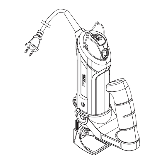
- Page 6 KNOW YOUR SPIN SAW ON/OFF switch Speed control wheel Hanging loop Assist handle Circle cutting knob Spindle locking button Freehand cutting guide collar Pivot point Locking Locking knob lever Collet nu Freehand guide foot Circle cutting Pivot point Mounting disc guide Mounting insert...
- Page 7 Guide handle Guide handle Plunge depth Spindle stop locking button Plunge guide Depth stop locking knob Vacuum attachment Edge guide locking knob Plunge depth turret Router base - 06 -...
- Page 8 ASSEMBLY AND OPERATING WARNING: Some of the following symbols may appear on this tool. Study these symbols and learn their meanings. Proper interpretation of these symbols will allow for more efficient and safer operation of this tool. INSTALLING THE ASSIST HANDLE The removable assist handle is designed for use when precision control over the tool movement is desired.
- Page 9 INSTALLING FREEHAND CUTTING GUIDE The freehand cutting guide is designed for basic freehand cutting with the cutting bit. It is ideally suited for cutting electrical outlet holes in drywall. WARNING: Do NOT use the freehand cutting guide with router bits. The amount of control this accessory provides is insufficient and could cause you to lose control and cause serious injury.
- Page 10 INSTALLING CUTTING BITS – cont’d Depress the shaft locking button (1) and rotate the collet lock nut (2) with the other hand until the locking button drops into place, preventing the shaft from turning (Fig. 3). While continuing to hold the shaft locking button IN, use the collet wrench (3) to turn the collet nut counter-clockwise.
- Page 11 CHANGINGING THE COLLET The cutting bits for this tool are locked into place with a collet nut (1) and collet (2) (Fig. 4). 1/8" and 5/32" collets are used for holding 1/8" and 5/32" cutting bits and hobby tool accessory bits. The 5/32" square collet is used to connect the flexible shaft to the tool. The 1/4" collet is supplied for holding 1/4"...
- Page 12 SPEED CONTROL SWITCH The spin saw is equipped with a variable speed control located below the ON/OFF switch. To run the tool at the slowest speed, rotate the speed control wheel (2) to number “1” (Fig. 6). To increase the tool speed, rotate the speed control wheel in the opposite direction. Maximum speed will be achieved at “6”.
- Page 13 ADJUSTING THE FREEHAND CUTTING GUIDE – cont’d Before starting to cut, double check the bit depth. Make sure the cutting guide is at a right angle to the bit and securely tightened. Double check the collet to make sure the bit is securely fastened.
- Page 14 NOTE: Refer to the above chart for materials, material thickness, speed of the tool and recom- mended cut feet per minute to be used with the various cutting bits. The speeds referenced chart are intended as a guide only and must be adjusted according to hardness, density and characteristics of the material being cut.
- Page 15 WARNING: Before turning the power switch ON, make sure you are holding the tool firmly with both hands. Starting torque will cause the tool to twist. Turn the switch ON. Fig. 8 Fig. 9 PRACTICE CUTS USING THE FREEHAND CUTTING GUIDE – cont’d When the motor is up to full speed, slowly tip the tool to an upright position, letting the bit cut into the workpiece (Fig.
- Page 16 CUTTING TIPS – cont’d Slower cutting gives you better control. Excessive pressure or fast cutting will increase the bit temperature and shorten the life of the bit. When cutting a hole in a vertical surface, avoid ending the cut at the bottom of the hole. Always start and end the cut at the “top”...
- Page 17 CUTTING OUTLET OPENINGS IN DRYWALL – cont’d The completed electrical box cut out will be accurately and neatly cut (Fig. 11). NOTE: Always move the cutting bit in a counter- clockwise direction around the outlet box. The natural tendency of the cutting bit to move to the left will make it easier to cut close to the box. Fig.
- Page 18 NOTES: Make sure the boss (7) on the cutting guide mounting disc goes through the hole in the circle guide. Do not over tighten the circle cutting guide mounting plastic parts. Hand tighten only. Adjust the circle cutting guide radius by loosening the pivot point knob (8), sliding it to the correct circle radius and re-tightening in the desired location.
- Page 19 NOTE: DO NOT let the bit touch the workpiece before switch is turned ON and the tool is up to full speed. Turn the switch ON. When the motor is up to full speed, slowly tip the tool and circle cutting guide assembly to an upright position, letting the bit cut into the workpiece (Fig.
- Page 20 ROUTER ACCESSORY INSTALLATION Remove any accessory already installed on the tool. Turn the router base locking knob (1) counter clockwise until it no longer protrudes inside the mounting collar (2) (Fig. 15). Slide the router base mounting collar onto the bottom of motor housing (3). Align the spindle locking button (4) with the spindle locking button opening (5).
- Page 21 ROUTER ACCESSORY INSTALLATION - cont’d Turn the router base locking knob clockwise until it locks into the locking knob hole in the motor housing. NOTE: Hand tighten only. If required, attach a vacuum to the vacuum adaptor (7). SETTING THE ROUTER DEPTH FOR SINGLE DEPTH ONLY Depth of cutting is controlled by sliding the router base up and down on the guide rods and locking it in place.
- Page 22 SETTING THE PLUNGE DEPTH Up to six different plunge depths can be pre-set by using the depth stop rod and the plunge action turret. This provides for quick changes between depth settings. Loosen the depth stop locking knob (1) counter clockwise and raise the depth stop rod (2) to its maximum height and then retighten the locking knob to hold the depth rod in position (Fig.
- Page 23 FREEHAND ROUTING Use the router base with small router bits to perform various freehand routing projects (Fig. 19). Remove 1/8" collet and insert 1/4" collet (Fig.). Install the router bit and securely tighten (Fig. 3). Adjust router base height to the correct routing depth (Fig. 17). Turn the switch ON making sure the router bit is not touching the workpiece.
- Page 24 CUTTING A CURVED LINE WITH A TEMPLATE – cont’d Make a template from hardboard or other similar material to the shape you require (Fig. 21). NOTE: The radius of curve must be greater than 2 1/2" for the router base to properly follow the curved template.
- Page 25 CUTTING WHILE USING THE STRAIGHT EDGE GUIDE NOTE: After setting the edge guide to the desired position, make a test cut on a scrap piece of material to verify you have the correct setting. Clamp the workpiece to hold it securely while cutting. NOTE: Make sure there is adequate clearance under the workpiece for the bit to travel and the edge is clear for the straight edge guide to move freely.
- Page 26 Turn the spin saw motor switch OFF and remove plug from the power source. Open the flexible shaft mounting collar (1) by pulling the quick release lever (2) outward (Fig. 25). Align the flexible shaft mounting collar with the motor housing (3). NOTE: Carefully align the square flexible shaft centre core so it will engage into the square hole in the collet.
- Page 27 INSTALLING A CUTTING BIT INTO THE FLEXIBLE SHAFT To insert a cutting bit into the flexible shaft collet, pull the shaft locking collar (1) back (Fig. 26). While holding the shaft locking collar back, rotate collet nut (2) until the shaft locking collar engag- es the shaft.
- Page 28 Shenzhen Take Tools Co., Ltd. Web: www.tacklifetools.com Facebook: www.facebook.com/Tacklife.US E-mail: support@tacklife.net ADD: No.B714,Niulanqian Building, Minzhi Road, Longhua District, Shenzhen, Guangdong, China 518000...
Need help?
Do you have a question about the PTR01A and is the answer not in the manual?
Questions and answers