Table of Contents
Advertisement
Quick Links
The Challenge Machinery Company provides owner's manuals on its
products solely as a courtesy to its customers. See the information below
before using this manual.
These manuals are for reference only. These manuals include products which are noncurrent,
unsupported or no longer produced by The Challenge Machinery Company, and are provided solely as
an accommodation to our customers. By providing these manuals, The Challenge Machinery Company
makes no representation or warranty as to the products, their current condition, or their suitability or fitness
for use in any particular application, which are the sole and independent responsibility of the product
owner and user.
Older products may not comply with current safety procedures, guidelines or regulations, and it
is the product owner's and user's responsibility to evaluate the suitability and fitness of the
products in their current use and application. The Challenge Machinery Company makes no
representation, warranty or recommendation regarding any modifications which may be required
on non-current or unsupported products. The Challenge Machinery Company assumes no liability
for any modification or alteration to any Challenge product, and any such modification or
alteration to any Challenge product is not authorized by The Challenge Machinery Company. The
availability of these manuals is solely for the purpose of providing reference information for the products.
This manual may not be complete in all aspects of product maintenance and repair. All products should
be used only by qualified and properly trained personnel, following proper safety procedures. All
products should be regularly inspected and maintained, and their condition, application and use should
be periodically evaluated by qualified personnel. Only qualified and properly trained technicians should
perform maintenance, repair and replacement procedures. Attempting these procedures without proper
training may cause machine damage or operator injury!
Products may be unsupported by The Challenge Machinery Company due to age or the unavailability of
parts from their original manufacturer. No parts or product support will be available to repair or maintain
unsupported products. Older products may not be UL listed (if the product does not have a UL label it is
not a listed product), and may not comply with applicable installation or other regulations or requirements
if relocated to a new facility. Many municipalities require a product to be UL listed before an electrician
will connect power to them. Often the cost of updating an older product to comply with current safety
regulations is greater than the value of the product.
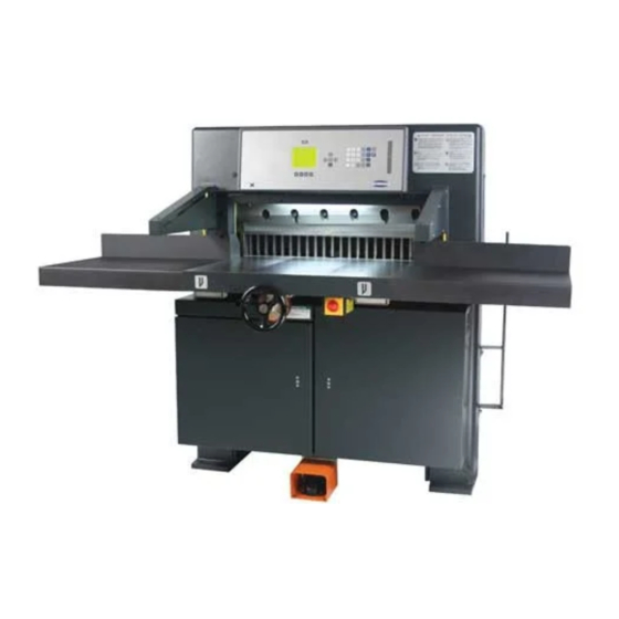
CHAMPION 305
Manual Backgauge
Instruction and Parts Manual
Serial Numbers:
1301708 through 1599999,
305M-J-150000 and up
Sold and Serviced by
The Challenge Machinery Company
6125 Norton Center Drive
Norton Shores, MI 49441-6081 USA
F.194-J
ChallengeMachinery.com
May 2019
Advertisement
Table of Contents

Related Manuals for Challenge CHAMPION 305

Summary of Contents for Challenge CHAMPION 305
- Page 1 Products may be unsupported by The Challenge Machinery Company due to age or the unavailability of parts from their original manufacturer. No parts or product support will be available to repair or maintain unsupported products.
-
Page 2: Introduction
Fill out the warranty card accompanying your machine and return it DIRECTLY TO CHALLENGE. If you bought a used machine, it is important to have the following information on record at Challenge. Copy this page, fill in the information and send it care of The Challenge Service Department, 6125 Norton Center Drive ... -
Page 3: Table Of Contents
1.0 Introduction TABLE OF CONTENTS 1.0 Introduction ............................2 2.0 Safety ..............................6 2.1 Precautions ...........................6 2.2 Power Lockout Procedure ......................6 2.3 Warning Label Definitions ......................7 3.0 Packing List ............................9 4.0 Specifications ..........................10 5.0 Footprint ............................11 6.0 Installation & Setup ........................12 6.1 Inspecting Shipment ........................ - Page 4 1.0 Introduction 11.1 Recommended Hydraulic Oil ....................35 11.2 Changing the Oil ........................35 11.3 Hydraulic Valve Adjustments ....................36 12.0 Adjustments ..........................41 12.1 Electric Eye Alignment ......................41 12.2 Backgauge Gib Adjustment ...................... 42 12.3 Squaring the Backgauge ......................43 12.4 Backgauge Position Accuracy Adjustment ................
- Page 5 1.0 Introduction 15.25 Line Light Assembly......................117 15.26 Compressor Assembly......................118 15.27 Encoder Cable Assembly ....................119 15.28 Knife Latch Assembly ......................120 15.29 Power Panel Connection Procedure Label (Fuses) ............121 15.30 Power Connection Procedure Label – Circuit Breakers ............122 15.31 Air Table Blower Assembly (For Air Table Option) ..............
-
Page 6: Safety
2.0 Safety 2.0 Safety 2.1 Precautions This machine is designed for one-person operation. Never operate the machine with more than one person. Safe use of this machine is the responsibility of the operator. Use good judgment and common sense when working with and around this machine. -
Page 7: Warning Label Definitions
2.0 Safety 2.3 Warning Label Definitions The following warning labels are found at various locations on your machine. Read and understand the meaning of each symbol. If a label is lost from the machine, it should be replaced. . HAZARDOUS AREA Disconnect power before cleaning, servicing, or making adjustments not requiring power. - Page 8 2.0 Safety !OJO! This Este simbolo de alerta de seguridad significa ¡ OJO ! - INSTRUCCIONES DE SEGURIDADPERSONAL. Lea las instrucciones porque se refieren a su seguridad personal. Fall de obedecer las instrucciones que siguen podria resultar en lesiones corporales. ...
-
Page 9: Packing List
3.0 Packing List 3.0 Packing List Part No. Description Qty. Basic Machine Extension Side Tables: 47166 18 x 24 Steel Side Table 47164-1 Side Table Back Plate H-6913-606 Side Table Bolts H-6424-6 Side Table Hex Nuts H-6939-616 Leveling Screws H-6913-6008 Side Table Mounting Bolts (shipped installed) H-7321-6... -
Page 10: Specifications
Optional: 3 Phase, 50 Hz AC; 220V or 380V , 1 Phase – phase converter kit K-3482 Electric Eyes – E-3370 Response time = 68 ms Object detection capability = 12 mm Challenge reserves the right to make changes to any product or specification without notice and without incurring responsibility to existing units. -
Page 11: Footprint
5.0 Footprint 5.0 Footprint... -
Page 12: Installation & Setup
6.0 Installation & Setup 6.0 Installation & Setup 6.1 Inspecting Shipment This machine has been carefully packed to prevent damage during shipment. However, claims for damage or loss are the responsibility of the recipient. Inspect all shipments as soon as they are received. -
Page 13: Moving Instructions
The table surface is cast iron, and it will rust if left unprotected. Coat the table with a non- abrasive wax. A Cutter Care Kit, p/n 16077, with cleaner and wax, is available through your Authorized Challenge Dealer. The protective film on the console may be removed. Never clean console with petroleum based solvents. Damage will result. -
Page 14: Hydraulic Power Unit Removal
If installation requires that the machine pass through a doorway that is less than 49” but greater than or equal to 42” wide, the machine should have been ordered from Challenge “knocked down” with the table removed. If the machine must fit through a doorway that is less than 42” and greater than or equal to 24-1/2”, the hydraulic power unit must be removed on-site. -
Page 15: Power Hook-Up
6.0 Installation & Setup 6.9 Power Hook-Up For satisfactory operation, be sure that your cutter is wired for the correct phase and voltage and has adequate power. The correct electrical specifications for your machine are shown on the serial plate. Check the machine serial plate before connecting the power. - Page 16 6.0 Installation & Setup CUSTOMER CUSTOMER GROUND SCREW GROUND SCREW CUSTOMER HOOK-UP CUSTOMER HOOK-UP TERMINAL BLOCKS TERMINAL BLOCKS STARTER RELAY MSCE1 TRANSFORMER TRANSFORMER OVER- LOAD RELAY OVER- LOAD STARTER RELAY MSCE1 RELAY TERMINAL TERMINAL BLOCKS BLOCKS PCF1 FUSE PCF5 FUSE PC BOARD PC BOARD CONTROLLER...
-
Page 17: Operation
IMPORTANT: DO NOT ATTEMPT TO OPERATE THE CUTTER UNTIL YOU HAVE THOROUGHLY READ AND UNDERSTAND ALL OF THE FOLLOWING INSTRUCTIONS. CALL YOUR AUTHORIZED CHALLENGE DEALER IF YOU STILL HAVE ANY QUESTIONS. 7.1 Power – Main Switch Power is applied to the machine when the main power switch is turned to the “ON” position (Figure 7). -
Page 18: Presetting The Backgauge
7.0 Operation 7.3 Presetting the Backgauge The backgauge must be preset every time the power is turned on. Using the hand wheel, turn the backgauge until it passes forward through the 5” position. The display readout will then show the correct backgauge position. -
Page 19: Turning Off The Hydraulic Motor
(Figure 9), then square it to the backgauge for cutting. Figure 9 Additional jogging aids can be purchased by contacting your authorized Challenge dealer. Always remove the jogging aid from the table before making a cut. -
Page 20: Knife Down Mode
7.0 Operation 7.13 Knife Down Mode The knife down mode is used to send the knife and clamp to the down position without returning up. This provides a way for the service technician to adjust the knife. To send the knife down or up, enter maintenance mode, “A”. -
Page 21: Operating Tips
7.0 Operation NOTE: The backgauge will not move to a position less than 2" (51 mm) when the false clamp plate is installed in the clamp. When the false clamp plate is not in use, store it on top of the cutter, with the locator pegs inserted into the 3 holes in the top cover 7.16 Operating Tips ... -
Page 22: Knife Installation/Changing
8.0 Knife Installation/Changing 8.0 Knife Installation/Changing Changing knives can be very dangerous unless safety precautions are observed and extreme care is taken when handling knives. Make sure knife lifters are properly installed, see instructions following. Keep handling of unprotected knives to an absolute minimum. ... -
Page 23: Knife Removal
8.0 Knife Installation/Changing 8.1 Knife Removal 1. Clear the cutter table. Place chipboard directly under the knife to prevent nicking if the blade hits the table. On the screen menu choose “MAINT.” and then “Knife Adjust”. The menu will lead you through the rest of this step, then lock out the main power source as shown on page 6. -
Page 24: Knife Installation
8.0 Knife Installation/Changing Figure 15 7. Clear the table and put the empty knife scabbard on the table. DANGER: Used knives are heavy and still very sharp. Be careful to keep the edge away from your body and keep other people out of the area while handling the blade. - Page 25 8.0 Knife Installation/Changing 5. Place your fingers along the top edge of the scabbard and your thumbs in the holes in the knife. 6. Pull the knife up in its scabbard until the bevel is exposed. 7. Place the lifter on top of the knife and insert the knife lifter handles into the corresponding knife bolt holes (use the lowest holes) and thread the handles into the knife until they touch the scabbard.
-
Page 26: Knife Care Tips
8.0 Knife Installation/Changing 15. Tighten all the bolts and release the paper deflector. 16. Restore power to the machine and turn in ON. Send the knife to the “UP” position as previously instructed. 17. Make a test cut through a full lift of stock. Make minor adjustments by loosening the bolts and repeating steps 9 through 11. -
Page 27: Cutting Stick
4 times again. 8.3.3 Bevel Angle Challenge recommends that bevel angles for the Champion 305 knives be in the range of 21° to 23°. In general, a 21° bevel angle will provide better cut quality when cutting soft paper (such as newsprint), recycled paper, or bound books. - Page 28 8.0 Knife Installation/Changing NOTES...
-
Page 29: Maintenance Section
Challenge. The Challenge Machinery Company assumes no liability for any modification or alteration to any Challenge products, and any such modification or alteration to any Challenge product is not authorized by The Challenge Machinery Company. Any... -
Page 30: Cleaning
5. Apply a paste wax (Challenge P/N 16078) to the table to seal the pores of the metal. Note: Do not use a wax that contains a cleaning compound on the table. The cleaner contains microscopic abrasive particles that will cause wear between the table and the bottom of the backgauge. -
Page 31: Console
9.0 Cleaning cleaner if the excess silicone is not removed. If the excess is not removed, the silicone spray has a substance that holds the silicone to the surface it is sprayed on that causes a black, gummy build-up under the backgauge. If a silicone spray is used, paper toweling must be used to remove the excess to prevent this wear and build-up. -
Page 32: Lubrication
10.0 Lubrication 10.0 Lubrication A clean, lubricated machine will cut more accurately, run longer, with less downtime, and fewer repairs. Schedule lubrication maintenance both early in the day and early in the week. This allows the lubricants to work into the machine. Lubrication at the end of the day or week allows the lubricants to run off without any benefit to the machine. - Page 33 10.0 Lubrication Knife bar pull-down pin (oil): Figure 20 Left and right clamp guides (grease): Figure 21 Lower knife and clamp cylinder pins (oil): Figure 22...
- Page 34 10.0 Lubrication Handwheel gears and shaft (grease): Figure 23 Wipe down the knife bar to remove dust and debris (Figure 24). Knife Bar Figure 24 Check knife bar link, bell crank, and hydraulic cylinder pin keepers to make sure they are in place and secure (Figure 25).
-
Page 35: Hydraulic System
The hydraulic fluid should be changed YEARLY or EVERY 1,000 HOURS of operation. The oil filter (Challenge part H-227-1) should be changed YEARLY or whenever any repairs are made to the hydraulic system. -
Page 36: Hydraulic Valve Adjustments
11.0 Hydraulic System Reservoir Tank Cover Hydraulic Tank Figure 26 3. Using a hand drill and transfer pump commonly found at hardware and home improvement stores, transfer the used oil to empty containers. 4. Remove the magnet stuck to the bottom of the tank. Clean off any debris that may be attached to it. - Page 37 11.0 Hydraulic System For initial setup, adjust the valves in the following order: 1. Main System Relief Valve- 1800 psi 2. Knife down sequence valve- 1600 psi 3. Clamp up relief valve- 400-600 psi 4. Pressure reducer valve- 1400max/400min psi 5.
- Page 38 11.0 Hydraulic System a. Open the left access door on front of the cutter. b. Press the cut buttons while reading the pressure on the main system pressure gauge (front gauge). The gauge should read approximately 1600 psi as the knife is moving down (when bottomed, the gauge will jump to 1800 psi showing the Main System Relief Pressure previously set).
- Page 39 11.0 Hydraulic System a. Loosen the lock knob. There are two knobs, one behind the other. The outer is the adjusting knob. The inner is the lock knob. b. Push the cut buttons and check the reading on the clamp gauge (rear gauge) when the clamp is on the table and the knife is coming down.
- Page 40 11.0 Hydraulic System 5.000 Set Maximum > Press /\ to Increase Press \/ to Decrease A) Main C) Send B) Job D) Exit d. Setting the Minimum Pressure: Perform a cut cycle, after the clamp has contacted the table and while the knife bar is coming down, read the pressure on the right hand pressure gauge.
-
Page 41: Adjustments
12.0 Adjustments 12.0 Adjustments Several of the following tests require the machine to be operational for checking and adjusting. Be very careful that tools and other people are clear of moving parts and that the cutter is not accidentally operated while adjustments are being made. Whenever working on the machine, disconnect the power and lock it out (see SAFETY PRECAUTIONS, page 6) unless the directions specifically require the machine to be powered. -
Page 42: Backgauge Gib Adjustment
12.0 Adjustments Outer Mounting Screws Inner Mounting Screws Figure 29 3. Loosen the inner mounting screws (Figure 29) to rotate the beams until they are aligned over their width. When the indicator lights indicate proper alignment as shown in Figure 28, tighten all screws. -
Page 43: Squaring The Backgauge
12.0 Adjustments Set Screws & Jam Nuts Rail Figure 31 To adjust: 1. Send the backgauge back to approximately 28” (711mm) and disconnect the power. 2. Always adjust the side gib first. Loosen all jam nuts and adjusting screws then tighten the front and rear screws. -
Page 44: Backgauge Position Accuracy Adjustment
12.0 Adjustments To adjust squareness: 1. As machine wears, make sure the backgauge gibs are set properly first (see Backgauge Gibs), then follow steps 2 through 5. NOTE: Gib adjustment is not necessary on initial machine setup because they have been adjusted at the factory. -
Page 45: Knife Latch Adjustment
12.0 Adjustments 4. If the backgauge position readout is off, you will have to adjust the accuracy. This parameter provides a means for adjusting the accuracy of the backgauge. To change the accuracy, move the backgauge to 2 inches (50.8mm) and cut paper. Measure the paper, and type in what you actually measure. -
Page 46: Line Light Adjustment (Incandescent Type)
12.0 Adjustments 7. Tilt the control console back up and secure it with the two screws. Restore power to the machine and perform a cut cycle. Recheck the gap to make sure it is still within the correct range. 8. Also make sure that the distance between the knife blade edge and the bottom surface of the clamp is greater than the knife latch gap. -
Page 47: Line Light Adjustment (Led Type)
12.0 Adjustments To adjust line light: 1. Let the console down by removing the two screws at the top. 2. Place a wide sheet(s) of paper on the cut stick to view the line. 3. Using a 3/16” hex wrench, turn one of the cap screws until you see a 1/16-1/8” beam. 4. -
Page 48: Proximity Switches
Be very careful that tools and other people are clear of moving parts and that the cutter is not accidentally operated while adjustments are being made. Challenge Champion cutters incorporate proximity switches to detect stages of operation. These types of limit switches have no moving parts and are more reliable than the old style of contact switches. - Page 49 12.0 Adjustments The Knife Up and Knife Down Proximity switches are mounted to a bracket that is attached to the Knife Cylinder (Figure 38). With the power off, set the collar between the proximity switches and then turn on power. Press cut buttons once to turn on the hydraulic motor. The knife will move to the absolute top of its stroke.
-
Page 50: Clamp Return Speed Adjustment
12.0 Adjustments actuator on the top of the clamp and must be adjusted to within 1/8” (3.2mm) of the face of the switch. Figure 40 12.9 Clamp Return Speed Adjustment The clamp return speed can be adjusted if it becomes too sluggish or too fast. This adjustment is made on the air cylinder that is attached to the clamp. -
Page 51: Pre-Clamp Pressure Adjustment
12.0 Adjustments 12.10 Pre-Clamp Pressure Adjustment The pre-clamp feature of the Champion 305 uses low-pressure pneumatics to bring the clamp down prior to making a cut. The system pressure is set at the factory and allows for safe and proper operation of the clamp. -
Page 52: Clamp Cylinder Adjustment (Clamp Height)
12.0 Adjustments Lower Flow Control Valve Figure 43 12.12 Clamp Cylinder Adjustment (Clamp Height) If the clamp piston bottoms in the cylinder before the clamp makes contact with the table, or if the clamp does not make full travel on the up stroke, the clamp cylinder may need adjustment. To adjust: 1. -
Page 53: Clamp Parallel Rod
12.0 Adjustments 4. Use the flats on the clamp cylinder shaft to turn the shaft into or out of the clevis as required, (in decreases, out increases height). The clamp should be set to 4” above the table. 5. Retighten the jam nut securely. 12.13 Clamp Parallel Rod If the clamp is not parallel with the table: 1. -
Page 54: Knife Bar Gibs
12.0 Adjustments Figure 46 – Jam Nut Location 12.15 Knife Bar Gibs The knife bar gibs are two steel backed UHMW plates on either side of the arch that guide and hold the knife as it cuts. If adjusted too tight the knife may not come down, or scoring could damage the gibs and knife bar. - Page 55 12.0 Adjustments 3. Adjust center (2) screws until snug - not tight to eliminate the air gap between the knife bar and gib. Tighten those (2) jam nuts. 4. Place the machine into knife down adjustment mode. See Operating instructions for your machine’s model.
-
Page 56: Repair And Replacement
13.0 Repair and Replacement 13.0 Repair and Replacement 13.1 Fuses (skip this section if the machine has Circuit Breakers) FIRE HAZARD. Replace only with same type and rating fuse. Figure 48 The Champions each have a set of fuses. The fuses are located inside the main power box, (Figure 48). - Page 57 13.0 Repair and Replacement E-Ring (Both Ends) Clevis Pin with 1/4-20 Threaded Hole Clevis Jam Nut Proximity Switch Actuator Proximity Switch Bracket Knife Cylinder Hose Connections Pin Keeper Sequence Valve Lower Pin Assembly Figure 49 6. Remove the clevis pin out of the knife bar and clevis by first removing the front E-style retaining ring on the pin (Figure 49).
- Page 58 13.0 Repair and Replacement Clamp Knife Frame Table 4-1/8” Figure 50 12. Lock the jam nut securely in place. 13. Reconnect the hydraulic hoses. CRUSH HAZARD! Knife and clamp will return to the up position when the key is turned on and the cut buttons are pressed for the first time. Keep hands and tools away.
-
Page 59: Troubleshooting
14.0 Troubleshooting 14.0 Troubleshooting Never work on this machine with the power on unless the instructions say the machine power must be on. Lock the power off at the wall disconnect switch. See Power Lockout Procedure, page 6. WON’T START 1. - Page 60 14.0 Troubleshooting CONCAVE CUTTING- ENDS WIDE, CENTER NARROW 1. Excessive moisture at edges of paper 2. More ink on edges of lift CONCAVE CUTTING- VARIATION OF TOP AND BOTTOM 1. Soft stock not firmly clamped 2. Knife is dull or ground incorrectly 3.
- Page 61 14.0 Troubleshooting 2. Knife bar has play- tighten gibs 3. Backgauge gibs loose 4. Dull knife 5. Clamp not parallel to table 6. Accuracy not set correctly BACKGAUGE MOVEMENT ERRATIC 1. Backgauge gibs loose or binding on table way (rail under table) 2.
-
Page 62: Menu Tree
14.0 Troubleshooting 14.1 Menu Tree... -
Page 63: Diagnostic Led's
14.0 Troubleshooting 14.2 Diagnostic LED’s The following is a description of the various diagnostic LED’s in the power panel. These lights are indicators used to show input and output status. -
Page 64: Description Of Error Messages
14.0 Troubleshooting 14.3 Description of Error Messages Error Message Description Test Checksum Error Bad program chip Replace EEPROM Clamp Up Failure Clamp failed to return to up position Clamp up sequence valve; within 7 seconds solenoid (cut) valve Clamp Down Failure Clamp failed to come down Solenoid valves;... -
Page 65: Sensor Data Abbreviations
14.0 Troubleshooting 14.4 Sensor Data Abbreviations RGHTCUT Right Cut Button Under RHS of table front LEFTCUT Left Cut Button Under LHS of table front CUTRLY (input) Cut Relay On power panel HYDLAT Hydraulic Latch Relay Main pc board KNFDWN Knife Down Proximity Switch On bracket attached to knife cylinder PRESET Preset Sensor... -
Page 66: Schematics & Parts Lists
15.0 Schematics & Parts Lists 15.0 Schematics & Parts Lists 15.1 Main Assembly – Frame/Tank 47900 Sheet 1... - Page 67 15.0 Schematics & Parts Lists 47900 Sheet 1 – Parts List PART NO. DESCRIPTION OF ACCESSORIES MAGNET –HYDRAULIC RESERVOIR 47513 47542 HPU WELDMENT GASKET – HYDRAULIC RESERVOIR 47543 WELDMENT – 305 FRAME 47901 H-238-4 STRAINER H-338 DIFFUSER ELBOW – PIPE, 90 DEGREE ¾ NPT H-503 NIPPLE –...
-
Page 68: Main Assembly - Hydraulics
15.0 Schematics & Parts Lists 15.2 Main Assembly – Hydraulics 47900 Sheet 2... - Page 69 15.0 Schematics & Parts Lists 47900 Sheet 2 – Parts List PART NO. DESCRIPTION OF ACCESSORIES 4411 CLEVIS - CONN. ROD L.H. 5136 PRESSURE REDUCING VALVE 8835-1 PIN KEEPER 40016-5 MOUNT - VIBRATION 47092 GUARD - FAN 47110-1 PIN - BELL CRANK 47171-1 BRACKET - CLAMP PROX 47172-1...
-
Page 70: Main Assembly - Clamp
15.0 Schematics & Parts Lists 15.3 Main Assembly – Clamp 47900 Sheet 3... - Page 71 15.0 Schematics & Parts Lists 47900 Sheet 3 – Parts List PART NO. DESCRIPTION 4406-D-1 BELLCRANK ASM - R.H. CLAMP 4441-1 DEFLECTOR - PAPER, BLOCK 4461 ROD - CLAMP CONNECTOR 4465 CLEVIS - CONN. ROD R.H. 4466 CLEVIS - CONN. ROD L.H. 4504-2 BAR - CLAMP PULL DOWN 4506...
-
Page 72: Main Assembly- Electrical Components, Lower Front
15.0 Schematics & Parts Lists 15.4 Main Assembly– Electrical Components, Lower Front 47900 Sheet 5... - Page 73 15.0 Schematics & Parts Lists 47900 Sheet 5 – Parts List PART NO. DESCRIPTION 40016-8 MOUNT - VIBRATION 47033-3 FRONT ENCLOSURE 47645-1 CLAMP COMPRESSOR ASSEMBLY 47646 FOOT SWITCH BRACKET 47647 FOOT SWITCH BRACKET 47943 SHIELD - TABLE E-1172-10 SNAP-IN BUSHING E-1719 FOOTSWITCH GUARD E-2196-17...
-
Page 74: Main Assembly - Electrical Components, Upper
15.0 Schematics & Parts Lists 15.5 Main Assembly – Electrical Components, Upper 47900 sheet 6 (w/Fluorescent Table Light) - Page 75 15.0 Schematics & Parts Lists 47900 sheet 6 – Parts List (w/Fluorescent Table Light) PART NO. DESCRIPTION 16047 HINGE- MPS CONSOLE 47195 BRACKET - ARCH JUNCTION 47502 BRACKET - CONSOLE 47568-1 ASSEMBLY - KNIFE LATCH 47958 PROX SENSOR BRACKET 47959 LINE LIGHT BRACKET E-2626-6 TERMINAL STRIP (6P)
-
Page 76: Main Assembly - Electrical Components, Upper
15.0 Schematics & Parts Lists 15.6 Main Assembly – Electrical Components, Upper 47900 Sheet 6 (w/LED Table Light) - Page 77 15.0 Schematics & Parts Lists 47900 Sheet 6 – Parts List (w/LED Table Light) PART NO. DESCRIPTION 16047 HINGE- MPS CONSOLE 47195 BRACKET - ARCH JUNCTION 47502 BRACKET - CONSOLE 47568-1 ASSEMBLY - KNIFE LATCH 47958 PROX SENSOR BRACKET 47961 LINE LIGHT BRACKET - LOWER 47962 LINE LIGHT BRACKET - UPPER...
-
Page 78: Main Assembly - Air Table Option
15.0 Schematics & Parts Lists 15.7 Main Assembly – Air Table Option 47900 Sheet 7... - Page 79 15.0 Schematics & Parts Lists 47900 Sheet 7 – Parts List PART NO. DESCRIPTION 47578 BLOWER ASSEMBLY 47652 AIR CHANNEL COVER 47654-1 305 TABLE, AIR E-2189-2_X_14INCHES TUBING - CORRUGATED, FLEXIBLE - 14" E-2189-2_X_23INCHES TUBING - CORRUGATED, FLEXIBLE - 23" E-2191-2 3/4 CONDUIT FITTING H-6650-6 3/8 NPT PLUG - PLASTIC...
-
Page 80: Main Assembly - Table Mounting
15.0 Schematics & Parts Lists 15.8 Main Assembly – Table Mounting 47900 Sheet 8... - Page 81 15.0 Schematics & Parts Lists 47900 Sheet 8 – Parts List PART NO. DESCRIPTION 4171 CUT STICK - 305 4542 STOP - STICK, RH 47115-1 TABLE GUIDE - LH FRONT 47116-1 TABLE GUIDE - RH FRONT 47630 CUT STICK STOP 47654 305 TABLE, NON-AIR 47654-1...
-
Page 82: Main Assembly - Backgauge Assembly
15.0 Schematics & Parts Lists 15.9 Main Assembly – Backgauge Assembly 47900 Sheet 9 & 10... - Page 83 15.0 Schematics & Parts Lists 47900 Sheet 9 & 10 – Parts List Continued PART NO. DESCRIPTION 4510 GIB - BACKGAUGE NUT 8641-2 ACTUATOR - PRESET 47029 LEADSCREW NUT- 305 MANUAL B.G. 47030 LEADSCREW ASSEMBLY - 305 MANUAL B.G. 47043 PILLOW BLOCK ASSEMBLY - REAR 47045 COVER - ENCODER...
-
Page 84: Main Assembly - Knife
15.0 Schematics & Parts Lists 15.10 Main Assembly – Knife 47900 Sheet 11... - Page 85 15.0 Schematics & Parts Lists 47900 Sheet 11 – Parts List PART NO. DESCRIPTION 4449 KNIFE ADJUSTING SCREW 4501-2 KNIFE BAR 4503-3 LINK ASM - KNIFE BAR 4505 KNIFE BAR GIB 4507-2 PIN - KNIFE BAR LINK 4518 PIN - KNIFE LINK 8815 WASHER - 3/8 HEAVY 8835-2...
-
Page 86: Main Assembly - Covers And Labels
15.0 Schematics & Parts Lists 15.11 Main Assembly – Covers and Labels 47900 Sheet 12... - Page 87 15.0 Schematics & Parts Lists 47900 Sheet 12 – Parts List PART NO. DESCRIPTION 11145-1 RIVET - 3/16 41130 PLATE - SERIAL NUMBER 47001 COVER - REAR ARCH 47002-1 SHIELD - BACKGAUGE 47003 BRACKET - BACKGAUGE SHIELD 47019-1 GUIDE - RH REAR 47020-1 GUIDE - LH REAR 47033-3...
-
Page 88: Main Assembly - Table Extensions
15.0 Schematics & Parts Lists 15.12 Main Assembly – Table Extensions 47900 Sheet 13... - Page 89 15.0 Schematics & Parts Lists 47900 Sheet 13 – Parts List PART NO. DESCRIPTION 8815 WASHER - 3/8 HEAVY 16026 LH TABLE EXTENSION - 24X36 16027 RH TABLE EXTENSION - 24X36 16028 LH TABLE EXTENSION - 24X36, AIR 16029 RH TABLE EXTENSION - 24X36, AIR 47164-1 PLATE- EXTENSION TABLE 47164-2...
-
Page 90: Power Panel Assembly (W/ Fuses)
15.0 Schematics & Parts Lists 15.13 Power Panel Assembly (w/ Fuses) EE-3170-1 Sht. 1, Rev. D... - Page 91 15.0 Schematics & Parts Lists EE-3170-1 Sht. 1, Rev. D – Parts List PART NO. DESCRIPTION OF ACCESSORIES 47512 PANEL - POWER E-1089-41 TRANSFORMER - 208-230V "T1" E-1143 BRIDGE RECTIFIER - PANEL MOUNT E-1429-17 WIRE DUCT & COVER - 9" LONG E-1429-18 WIRE DUCT &...
- Page 92 15.0 Schematics & Parts Lists EE-3170-1 Sht. 1, Rev. D – Parts List, Continued PART NO. DESCRIPTION OF ACCESSORIES EE-2820-2 PROX. ASSEMBLY - KNIFE DOWN "K" EE-2820-5 PROX. ASSEMBLY - KNIFE UP "U" EE-3210 CABLE ASM. - CLAMP COMPRESSOR JUMPER EE-2821-8 CABLE ASM.
- Page 93 15.0 Schematics & Parts Lists EE-3170-1 Sht. 2, Rev. A (w/Fuses)
- Page 94 15.0 Schematics & Parts Lists Power Panel Asm. – Blower Opt. Wiring (w/Fuses) EE-3170-1 Sht. 3, Rev. A...
-
Page 95: Power Panel Assembly (W/Circuit Breakers)
15.0 Schematics & Parts Lists 15.14 Power Panel Assembly (w/Circuit Breakers) EE-3170-2 rev. “A”... - Page 96 15.0 Schematics & Parts Lists EE-3170-2 Sht. 1, Rev. A – Parts List, NO. PART NO. DESCRIPTION OF ACCESSORIES 47512 PANEL - POWER E-1089-41 TRANSFORMER - 208-230V "T1" E-1143 BRIDGE RECTIFIER - PANEL MOUNT E-1429-17 WIRE DUCT & COVER - 9" LONG E-1429-18 WIRE DUCT &...
- Page 97 15.0 Schematics & Parts Lists EE-3170-2 Sht. 1, Rev. A – Parts List, continued NO. PART NO. DESCRIPTION OF ACCESSORIES EE-2843-1 CABLE ASSEMBLY - KNIFE LATCH EE-2834-2 CABLE ASM. - JUNCTION BOX EE-2836-1 CONDUIT ASM. - HYDRAULIC MOTOR, 3 PHASE EE-2820 PROX.
- Page 98 15.0 Schematics & Parts Lists EE-3170-2 sh’t 2 rev. “A”...
- Page 99 15.0 Schematics & Parts Lists Power Panel Assembly – Blower Option Wiring (w/Circuit Breakers) EE-3170-2 sh’t 3 rev. “A”...
-
Page 100: Basic Machine Schematic W/Fuses
15.0 Schematics & Parts Lists 15.15 Basic Machine Schematic w/Fuses E-3171-3 Rev. B... -
Page 101: Basic Machine Schematic - Ergo Touch Models W/Fuses
15.0 Schematics & Parts Lists 15.16 Basic Machine Schematic – Ergo Touch Models w/Fuses E-3171-3 Rev. B... - Page 102 15.0 Schematics & Parts Lists...
-
Page 103: Basic Machine Schematic - Standard Cut W/Circuit Breakers
15.0 Schematics & Parts Lists 15.17 Basic Machine Schematic – Standard Cut w/Circuit Breakers E-3171-4 rev.”A”... -
Page 104: Basic Machine Schematic - Ergo Touch W/Circuit Breakers
15.0 Schematics & Parts Lists 15.18 Basic Machine Schematic – Ergo Touch w/Circuit Breakers E-3171-4 rev. “A”... -
Page 105: Interconnection Diagram
15.0 Schematics & Parts Lists 15.19 Interconnection Diagram E-3474 Rev. “B”... -
Page 106: Hydraulic Manifold Kit
15.0 Schematics & Parts Lists 15.20 Hydraulic Manifold Kit H-504-1, Rev. B PART NO. DESCRIPTION OF ACCESSORIES H-465-2 MANIFOLD ASSEMBLY H-242-37 HYDRAULIC HOSE ASSEMBLY (30" LONG) H-242-43 HYDRAULIC HOSE ASSEMBLY (21" LONG) H-242-84 HYDRAULIC HOSE ASSEMBLY (42" LONG) H-437-1 VALVE ASM. - KNIFE DOWN SEQUENCE HYDRAULIC HOSE ASSEMBLY (50”... -
Page 107: Knife Down Sequence Valve Assembly
15.0 Schematics & Parts Lists 15.20.1 Knife Down Sequence Valve Assembly H-437-1, Rev. D PART NO. DESCRIPTION OF ACCESSORIES 56162-1 TUBE ASM. 56167 ALUMINUM BODY - COUNTER BAL. VALVE KIT H-203-40 COUNTER BALANCE VALVE H-230-10 ELBOW- ORING TO TUBE H-230-6 ELBOW- O-RING TO TUBE H-434 CONNECTOR - ORING TO ORING... -
Page 108: Hydraulic Manifold Assembly
15.0 Schematics & Parts Lists 15.20.2 Hydraulic Manifold Assembly H-465-2, Rev. E PART NO. DESCRIPTION OF ACCESSORIES H-468-3 MANIFOLD - HYDRAULIC 8P-629-3 GAGE H-253-2 ADAPTER - PIPE TO TUBE H-425-1 TUBE ASSEMBLY - "G2" PORT H-230 ELBOW - 'O' RING TO TUBE H-6918-414 1/4-20 X 1-3/4"... -
Page 109: Hydraulic Manifold
15.0 Schematics & Parts Lists 15.20.2.1 Hydraulic Manifold H-468-3, Rev. C PART NO. DESCRIPTION OF ACCESSORIES H-427-4 PLUG - SAE H-427 PLUG - SAE PRESSURE REDUCING VALVE – MANUAL 5136 NAMEPLATE E-1069-17 COIL (24 VAC) H-427-5 SAE PLUG (220 IN-LB TORQUE) H-427-2 SAE PLUG SAE PLUG (180 IN-LB TORQUE) H-427... -
Page 110: Hydraulic Schematic
15.0 Schematics & Parts Lists 15.21 Hydraulic Schematic H-468-3, Rev. C... -
Page 111: Control Console Assembly
15.0 Schematics & Parts Lists 15.22 Control Console Assembly EE-2850-2, Rev. C (Front View) - Page 112 15.0 Schematics & Parts Lists EE-2850-2, Rev. A (Rear View)
-
Page 113: Cut Button Assembly
15.0 Schematics & Parts Lists 15.23 Cut Button Assembly EE-3374, Rev. C... - Page 114 15.0 Schematics & Parts Lists NOTES:...
-
Page 115: Cut Button Kit - Ergo Style Touch Switches
15.0 Schematics & Parts Lists 15.24 Cut Button Kit – Ergo Style Touch Switches K-3379, Rev. A... - Page 116 15.0 Schematics & Parts Lists K-3379, Rev. A, Continued...
-
Page 117: Line Light Assembly
15.0 Schematics & Parts Lists 15.25 Line Light Assembly S/N's: 1509999 and below S/N's: 305-J-151075 and below NOTE: For LED style line light (S/N's: 305-J-151076 and above), see Section 15.6 on page 76 for the LED line light assembly part number. 47538, Rev. -
Page 118: Compressor Assembly
15.0 Schematics & Parts Lists 15.26 Compressor Assembly 47645-1 Rev. E PART NO. DESCRIPTION OF ACCESSORIES 47644 COMPRESSOR E-1710-3 SPLIT TUBING 12" EE-3210 CABLE ASSEMBLY- COMPRESSOR POWER P-521 VALVE- 2-WAY, N.O. H-261-3 TEE- 1/4 MALE RUN, BRASS H-269-2 ELBOW - 90%%176 STREET, BRASS H-6406-407 NIPPLE- 1/4"... -
Page 119: Encoder Cable Assembly
15.0 Schematics & Parts Lists 15.27 Encoder Cable Assembly EE-2838-3 Rev A... -
Page 120: Knife Latch Assembly
15.0 Schematics & Parts Lists 15.28 Knife Latch Assembly 47568-1, Rev. A PART NO. DESCRIPTION OF ACCESSORIES 47505-1 PLATE- KNIFE LATCH MOUNT E-974-3 SOLENOID 47567 LINK- CHAIN H-5254-510 SCREW- 5/16 X 1-1/4 SOC. SHOULDER 47553-1 LINK ASSEMBLY- KNIFE LATCH 41117-1 SPRING- EXTENSION H-6451-0500 RETAINING RING- GRIPPING EXTERNAL... -
Page 121: Power Panel Connection Procedure Label (Fuses)
15.0 Schematics & Parts Lists 15.29 Power Panel Connection Procedure Label (Fuses) S-1781-161, Rev. B... -
Page 122: Power Connection Procedure Label - Circuit Breakers
15.0 Schematics & Parts Lists 15.30 Power Connection Procedure Label – Circuit Breakers S-1781-231 rev. “A”... -
Page 123: Air Table Blower Assembly (For Air Table Option)
15.0 Schematics & Parts Lists 15.31 Air Table Blower Assembly (For Air Table Option) 47578, Rev. C... -
Page 124: Paper Deflector Kit (Option)
15.0 Schematics & Parts Lists 15.32 Paper Deflector Kit (Option) AA-13936-1, Rev. A Kit includes the following parts: PART NO. DESCRIPTION A-4511-2 DEFLECTOR ASSEMBLY H-6918-616 3/8-16 X 2 SOCKET HEAD CAP SCREW H-6918-606 3/8-16 X 3/4 SOCKET HEAD CAP SCREW A-4497 LOCK STUD ASSEMBLY H-7324-12... -
Page 125: Deflector & Shaft Assembly (Part Of Paper Deflector Kit)
15.0 Schematics & Parts Lists 15.32.1 Deflector & Shaft Assembly (Part of Paper Deflector Kit) A-4511-2 PART NO. DESCRIPTION A-4524-2 DEFLECTOR AND SHAFT ASSEMBLY 4522-3 GUIDE - PAPER DEFLECTOR 4545 SPACER S-1193-25 1/4 'E' RING 47535 SPRING- DEFLECTOR, PAPER 4520 PIN - UPPER... - Page 126 15.0 Schematics & Parts Lists Safety System Tests Machine manufacturer CHALLENGE Model _305 manual backgauge Serial Number __________________ Frequency of test: THESE TESTS SHOULD BE PERFORMED AT THE BEGINNING OF EACH WORK DAY. Turn on the cutter and start the hydraulic motor (see operator’s manual for instructions). Enable the electric eye safety system.
- Page 128 F.194-J May 2019...
Need help?
Do you have a question about the CHAMPION 305 and is the answer not in the manual?
Questions and answers