Sign In
Upload
Manuals
Brands
Allied Telesis Manuals
Media Converter
AT-MCF2012LC/1
Allied Telesis AT-MCF2012LC/1 Converter Manuals
Manuals and User Guides for Allied Telesis AT-MCF2012LC/1 Converter. We have
2
Allied Telesis AT-MCF2012LC/1 Converter manuals available for free PDF download: Installation Manual, Specifications
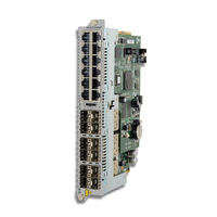
Allied Telesis AT-MCF2012LC/1 Installation Manual (190 pages)
Multi-channel Media Converter
Brand:
Allied Telesis
| Category:
Media Converter
| Size: 5.8 MB
Table of Contents
Table of Contents
5
Preface
13
How this Guide Is Organized
14
Where to Find Web-Based Guides
16
Contacting Allied Telesis
17
Online Support
17
Email and Telephone Support
17
Returning Products
17
Sales and Corporate Information
17
Warranty
17
Management Software Updates
17
Section I: Features
19
Chapter 1: AT-MCF2000 Multi-Channel Media Converter Series
21
Hardware Components
22
Table 1: Hardware Components
22
Management Software Components
25
Table 2: Management Software
25
Chapter 2: AT-MCF2000 and AT-MCF2300 Chassis
27
Figure 1: AT-MCF2000 and AT-MCF2300 Chassis
27
Figure 2: AT-MCF2000 Chassis Slots
28
Table 3: AT-MCF2000 Chassis Slots
28
Figure 3: AT-MCF2300 Chassis Sots
29
Table 4: AT-MCF2300 Chassis Slots
29
Chapter 3: AT-MCF2012LC, AT-MCF2012LC/1 and AT-MCF2032SP Modules
32
Overview
32
Figure 4: AT-MCF2000 Series Media Converter Module
32
Front Panels
33
Figure 5: Front Panel of the AT-MCF2012LC Module
33
Figure 6: Front Panel of the AT-MCF2012LC/1 Module
33
Figure 7: Front Panel of the AT-MCF2032SP Module
33
Media Converter Channels
34
Figure 8: Channel 1 on the Media Converter Module
34
Twisted Pair Ports
35
Table 5: Twisted Pair Cabling and Distances
35
Fiber Optic Ports
36
Table 6: Fiber Optic Ports
36
Channel Operating Modes
37
Link Test Mode
37
Missinglink Mode
37
Smart Missinglink Mode
39
Guidelines to Using the Channel Operating Modes
40
Port and Channel Leds
41
A" Activity LED
41
Figure 9: Activity LED for a Twisted Pair Port
41
Figure 10: Activity LED for a Fiber Optic Port on the AT-MCF2012LC and AT-MCF2012LC/1 Modules
41
L" Link Leds
42
Figure 11: Activity Leds for the Fiber Optic Ports on the AT-MCF2032SP Module
42
Figure 12: Link LED for a Twisted Pair Port
42
Table 7: "A" Activity LED
42
Figure 13: Link LED for a Fiber Optic Port on the AT-MCF2012LC and AT-MCF2012LC/1 Modules
43
Figure 14: Link Leds for the Fiber Optic Ports on the AT-MCF2032SP Module
43
Table 8: Link Leds in the Link Test Mode
44
Table 10: "L" Link Leds in the Smart Missinglink Mode
45
Table 9: "L" Link Leds in the Missinglink Mode
45
CDC and FDC Duplex Mode and Collision Leds
46
Figure 15: Duplex Mode and Collision Leds on the AT-MCF2012LC and AT-MCF2012LC/1 Modules
47
Figure 16: Duplex Mode and Collision Leds on the AT-MCF2032SP Module
47
Figure 17: Channel Operating Mode Leds on the AT-MCF2012LC and AT-MCF2012LC/1 Modules
48
ML, and SML Channel Operating Mode Leds
48
Table 11: CDC and FDC Duplex Mode and Collisions Leds
48
Figure 18: Channel Operating Mode Leds on the AT-MCF2032SP Module
49
Figure 19: RDY/FLT LED on the AT-MCF2032SP Module
49
Rdy/Flt Led
49
Table 12: RDY/FLT LED
49
Channel Leds
50
Figure 20: HBI and HBO Heartbeat Leds on the AT-MCF2032SP Module
50
HBI and HBO Heartbeat Leds
50
Mode Button
51
Figure 21: Mode Button
51
Figure 22: "CH" Channel Leds on the AT-MCF2012LC and AT-MCF2012LC/1 Modules
51
Figure 23: Channel Leds on the AT-MCF2032SP Module
52
Guidelines to Using the Media Converter Modules
53
Chapter 4: AT-MCF2000M Management Module
55
Overview
56
Figure 24: AT-MCF2000M Management Module
56
Front Panel
58
Figure 25: Front Panel of the AT-MCF2000M Management Module
58
10/100/1000Base-T Management Port
59
Table 13: Cable Requirements for the 10/100/1000Base-T Management Port
59
Terminal Port
61
Stack Port
62
Reset Button
63
Figure 26: Pressing the Reset Button
64
SD Slot
65
Chassis ID Jumper
66
Figure 27: Chassis ID Jumper
66
Leds
67
General Status Leds
67
Figure 28: General Status Leds
67
Table 14: General Status Leds
67
Terminal Port LED
68
Figure 29: Link/Activity LED on the RS-232 Terminal Port
68
Table 15: Link/Activity LED on the RS-232 Terminal Port
68
10/100/1000Base-T Management Port Leds
69
Figure 30: Link/Activity and Duplex-Mode Leds on the Management Port
69
Table 16: Link/Activity LED on the Management Port
69
Table 17: Duplex-Mode/Collisions LED on the Management Port
69
ID Leds
70
Stack Port LED
70
Figure 31: Chassis ID Number Leds
70
Figure 32: Link/Activity LED on the Stack Port
70
Secure Digital Memory Card Slot LED
71
Figure 33: SD Slot LED
71
Table 18: Link/Activity LED on the Management Port
71
Table 19: SD Slot LED
71
Chapter 5: AT-MCF2000S Stacking Module
73
Overview
74
Figure 34: AT-MCF2000S Stacking Module
74
Topology
75
Figure 35: Example Stack of Four Media Converter Chassis
75
Figure 36: Maximum Length of a Stacking Cable
75
Maximum Number of Media Converter Modules in a Stack
76
Cabling the Stack Ports
77
Figure 37: Cabling the AT-MCF2000M Management Module to the AT-MCF2000S Stacking Module
77
Table 20: Cable Requirements for the Stack Ports
77
Figure 38: Cabling Two AT-MCF2000S Stacking Modules
78
Chassis ID Numbers
79
Figure 39: Chassis ID Jumper on the AT-MCF2000M Management Module
79
Figure 40: Chassis ID DIP Switches on the AT-MCF2000S Stacking Module
80
Figure 41: Chassis ID Numbers
80
Leds
81
Table 21: Leds on the AT-MCF2000S Stacking Module
81
Chassis ID Leds
82
Guidelines to Building a Stack
83
Section II: Installation
85
Chapter 6: Reviewing the Safety Precautions
87
Chapter 6: Reviewing the Safety Precautions
88
Chapter 7: Selecting a Location
91
Chapter 7: Selecting a Location
92
Chapter 8: Unpacking the AT-MCF2000 or AT-MCF2300 Chassis
93
Table 22: AT-MCF2000 Chassis Items
93
Table 23: AT-MCF2300 Chassis Items
94
Chapter 9: Removing the Rubber Feet
97
Figure 42: Removing the Chassis Feet
97
Chapter 9: Removing the Rubber Feet
98
Chapter 10: Installing the AT-MCF2000AC or AT-MCF2300AC Power Supply Module
99
Figure 43: Removing the Blank Panel from a Power Supply Slot
99
Table 24: AT-MCF2000AC or AT-MCF2300AC Power Supply Module Items
100
Chapter 10: Installing the AT-MCF2000AC or AT-MCF2300AC Power Supply Module
100
Figure 44: Installing the AT-MCF2000AC Power Supply Module
101
Figure 45: Securing the AT-MCF2000AC Power Supply Module
101
Figure 46: Installing a Retaining Clip
102
Chapter 11: Installing the AT-MCF2KFAN Module
103
Figure 47: Removing the Cover from a Power Supply Slot
103
Table 25: AT-MCF2KFAN Module Items
104
Chapter 11: Installing the AT-MCF2KFAN Module
104
Figure 48: Installing the AT-MCF2KFAN Fan Module
105
Figure 49: Securing the AT-MCF2KFAN Fan Module
105
Chapter 12: Installing a Media Converter Module
107
Figure 50: Removing a Blank Cover from a Media Converter Slot
107
Figure 51: Removing the Battery Insulator
108
Table 26: AT-MCF2000 Media Converter Module Items
108
Chapter 12: Installing a Media Converter Module
108
Figure 52: Installing a Media Converter Module
109
Figure 53: Securing a Media Converter Module
109
Chapter 13: Installing the AT-MCF2000M Management Module
111
Figure 54: Removing the Blank Panel from the Management Slot
111
Table 27: AT-MCF2000M Management Module
112
Figure 55: Setting the Chassis ID Jumper on the AT-MCF2000M Management Module
113
Figure 56: Removing the Battery Insulator
113
Figure 57: Installing the Management Module
114
Figure 58: Securing the Management Module
114
Chapter 14: Installing the AT-MCF2000S Stacking Module
115
Figure 59: Removing the Blank Panel from the Management Slot
115
Table 28: AT-MCF2000S Module Items
116
Chapter 14, "Installing the AT-MCF2000S Stacking Module" on Page
116
Figure 60: Setting the Chassis ID DIP Switches
117
Figure 61: Installing the AT-MCF2000S Stacking Module
117
Figure 62: Securing the AT-MCF2000S Stacking Module
118
Figure 63: Labelling the AT-MCF2000S Stacking Module with the Chassis ID Number
118
Chapter 15: Installing the Chassis in an Equipment Rack
119
Figure 64: Attaching a Rack-Mount Bracket to the AT-MCF2000 Chassis
119
Figure 65: Attaching a Rack-Mount Bracket to the AT-MCF2300 Chassis
119
Figure 66: Rack-Mount Bracket Positions on the AT-MCF2300 Chassis
120
Chapter 15, "Installing the Chassis in an Equipment Rack" on Page
120
Figure 67: Invalid Rack-Mount Bracket Positions on the AT-MCF2300 Chassis
121
Chapter 16: Grounding the AT-MCF2300 Chassis
123
Figure 68: Stripping the Grounding Wire
123
Figure 69: Attaching the Grounding Wire to the Grounding Lug
123
Figure 70: Removing the Grounding Lug Screws
124
Figure 71: Attaching the Grounding Lug
124
Chapter 16: Grounding the AT-MCF2300 Chassis
124
Chapter 17: Installing the SFP Modules in the AT-MCF2032SP Module
125
Figure 72: Removing a Dust Cover from an SFP Slot
125
Figure 73: Installing an SFP Module
126
Figure 74: Positioning the SFP Handle
126
Chapter 17: Installing the SFP Modules in the AT-MCF2032SP Module
126
Chapter 18: Cabling the Ports on the Media Converter Module
129
Chapter 19: Cabling the AT-MCF2000M and AT-MCF2000S Modules
131
Figure 75: Connecting an Enhanced Category 5 Network Cable to the 10/100/1000Base-T Management Port
131
0 Chapter 1, “Installing the AT-MCF2AC or AT-MCF23AC Power
132
0 Chapter 11, “Installing the AT-MCF2KFAN Module” on Page 13
132
0 Chapter 12, “Installing a Media Converter Module” on Page 17
132
0 Chapter 13, “Installing the AT-MCF2M Management Module” on
132
0 Chapter 14, ”Installing the AT-MCF2S Stacking Module” on Page
132
0 Chapter 15, “Installing the Chassis in an Equipment Rack” on Page
132
0 Chapter 16, “Grounding the AT-MCF23 Chassis” on Page 123
132
0 Chapter 17, “Installing the SFP Modules in the AT-MCF232SP
132
0 Chapter 18, “Cabling the Ports on the Media Converter Module” on
132
0 Chapter 19, “Cabling the AT-MCF2M and AT-MCF2S Modules”
132
0 Chapter 6, “Reviewing the Safety Precautions” on Page 87
132
0 Chapter 7, “Selecting a Location” on Page 91
132
0 Chapter 8, “Unpacking the AT-MCF2 or AT-MCF23 Chassis” on
132
0 Chapter 9, “Removing the Rubber Feet” on Page 97
132
Figure 76: Cabling the AT-MCF2000M Management Module to the AT-MCF2000S Stacking Module
132
Chapter 19: Cabling the AT-MCF2000M and AT-MCF2000S Modules
132
Figure 77: Cabling Two AT-MCF2000S Stacking Modules
133
Chapter 20: Powering on the Chassis
135
Figure 78: Setting the ON/OFF Switch to the off Position
135
Figure 79: Raising the Retaining Clip
135
Figure 80: Connecting the AC Power Cord
136
Figure 81: Positioning the Power Cord Retaining Clip
136
Chapter 20: Powering on the Chassis
136
Chapter 21: Verifying the Installation
139
AT-MCF2000AC and AT-MCF2300AC Power Supply Module
140
AT-MCF2KFAN and AT-MCF2300FAN Modules
140
Chapter 21: Verifying the Installation
140
AT-MCF2012LC, AT-MCF2012LC/1 and AT-MCF2032SP Media Converter Modules
141
AT-MCF2000M Management Module
142
AT-MCF2000S Stacking Module
142
Chapter 22: Starting a Local Management Session
143
Figure 82: Connecting the RS-232 Serial Management Cable to the RS-232 Terminal Port
143
Figure 83: Command Line Prompt
144
Chapter 23: Troubleshooting the Modules
145
AT-MCF2012LC, AT-MCF2012LC/1 and AT-MCF2032SP Media Converter Modules
146
AT-MCF2000AC and AT-MCF2300AC Power Supply Modules
150
AT-MCF2KFAN and AT-MCF2300FAN Modules
151
Figure 84: Covering a Broken Fan on the AT-MCF2300FAN Module
152
AT-MCF2000M Management Module
153
AT-MCF2000S Stacking Module
155
Chapter 24: Replacing the Modules
157
Replacing a Media Converter Module
158
Figure 85: Labelling and Removing the Twisted Pair Cables and the Fiber Optic Cables
158
Figure 86: Installing the Dust Covers on the Fiber Optic Ports
158
Figure 87: Removing the SFP Modules from the AT-MCF2032SP Module
159
Figure 88: Removing the Media Converter Module
159
Figure 89: Installing the AT-MCF2KPNL1 Slot Cover over a Media Converter Slot
160
Replacing the AT-MCF2000M or AT-MCF2000S Module
161
Figure 90: Disconnecting the Cables from the AT-MCF2000M and AT-MCF2000S Modules
161
Figure 91: Removing the AT-MCF2000M Management Module or the AT-MCF2000S Stacking Module
162
Figure 92: Installing the AT-MCF2KPNL3 Slot Cover on the Management Slot
163
Replacing the AT-MCF2000AC or AT-MCF2300AC Power Supply
164
Figure 93: Setting the ON/OFF Switch to the off Position
164
Figure 94: Removing the Power Cord
165
Figure 95: Removing the AT-MCF2000AC or AT-MCF2300AC Power Supply Module
166
Figure 96: Installing the AT-MCF2KPNL2 Slot Cover over the Power Supply Slot
167
Replacing the AT-MCF2300FAN Module
168
Figure 97: Removing the Fan Cover
168
Figure 98: Removing the AT-MCF2300FAN Module
169
Figure 99: Installing a New AT-MCF2300FAN Module
170
Appendix A: Technical Specifications
171
Environmental Specifications
171
Standards
171
Safety and Electromagnetic Emissions Certifications
172
AT-MCF2000 Chassis
172
AT-MCF2300 Chassis
172
AT-MCF2000AC Power Supply Module
173
AT-MCF2300AC Power Supply Module
173
AT-MCF2012LC, AT-MCF2012LC/1 and AT-MCF2032SP Media Converter Modules
174
Specifications
174
Twisted Pair Port Pinouts
174
Table 29: 10/100Base-TX Port Pinouts
174
100Base-FX Fiber Optic Ports
175
Table 30: Fiber Optic Port Specifications for the AT-MFC2012LC Module
175
Table 31: Fiber Optic Port Specifications for the AT-MFC2012LC/1 Module
175
AT-MCF2000M Management Module
176
Specifications
176
10/100/1000Base-T Port Pin-Outs
176
Figure 100: RJ-45 Connector and Port Pin Assignments
176
Table 32: 10/100/1000Base-T Management Port Pinouts at 10 or 100 Mbps
176
Table 33: 10/100/1000Base-T Management Port Pinouts at 1000 Mbps
176
Terminal Port Pinouts
177
Figure 101: RS-232 Terminal Port Pinouts
177
Table 34: RS-232 Terminal Port
177
AT-MCF2000S Stacking Module
178
AT-MCF2KFAN Module
178
AT-MCF2300FAN Module
178
Appendix B: DIP Switch Settings for the AT-MCF2000S Stacking Module
179
Figure 102: Chassis ID DIP Switches on the AT-MCF2000S Stacking Module
179
Table 35: SW2 DIP Switch Settings (ID Numbers 1 to 15) for the AT-MCF2000S Stacking Module
179
Table 36: SW2 DIP Switch Settings (ID Numbers 16 to 30) for the AT-MCF2000S Stacking Module
180
Appendix C: Cleaning Fiber Optic Connectors
181
Figure 103: Ferrule in an SC Connector Plug
181
Figure 104: Unclean and Clean Ferrule
181
Using a Cartridge-Type Cleaner
182
Figure 105: Cartridge Cleaner
182
Figure 106: Rubbing the Ferrule Tip on the Cleaning Surface
183
Using a Swab
184
Figure 107: Lint-Free and Alcohol-Free Swabs
184
Figure 108: Cleaning a Recessed Ferrule
184
Index
187
Advertisement
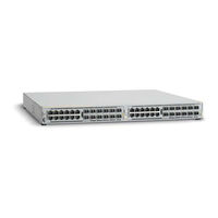
Allied Telesis AT-MCF2012LC/1 Specifications (5 pages)
Multi-channel Modular Media Chassis
Brand:
Allied Telesis
| Category:
Network Hardware
| Size: 0.08 MB
Table of Contents
Field Maintenance
2
Electrical Characteristics
4
Management Interfaces
4
Status Indicators
4
Ordering Information
5
Advertisement
Related Products
Allied Telesis AT-MCF2000
Allied Telesis AT-MCF2012LC
Allied Telesis AT-MCF2300
Allied Telesis AT-MCF2032SP
Allied Telesyn AT-MCF106LH
Allied Telesyn AT-MCF112SC
Allied Telesyn AT-MCF112VF
Allied Telesyn AT-MCF112SM
Allied Telesyn AT-MCF112LH
Allied Telesis AT-MCF106MT
Allied Telesis Categories
Switch
Network Router
Media Converter
Network Hardware
Wireless Access Point
More Allied Telesis Manuals
Login
Sign In
OR
Sign in with Facebook
Sign in with Google
Upload manual
Upload from disk
Upload from URL