
Related Manuals for PLAYSTAR Play Maker PS 7456


Summary of Contents for PLAYSTAR Play Maker PS 7456
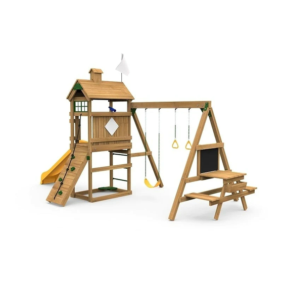
- Page 1 Play Maker ® Safety Guide & Building Instructions Front View Back View Pallet Area Requirements We’re Here To Help! 1-888-752-9782 PS 7456 Call Toll Free Customer Service: Monday - Friday, 8:00 to 5:00 C.S.T. A.M. P. M.
- Page 2 • Thoroughly read all safety instructions before Testing and Materials (ASTM) Home Playground beginning. Safety Standard. In order for PlayStar to comply with the ASTM Standard, we cannot recommend • Children must remain clear of construction site until anyone above these limits.
-
Page 3: Annual Maintenance Checklist
SAFETY INSTALLATION: 1. On-site adult supervision is recommended strangulation hazard. for children of all ages. 3. Verify that suspended climbing ropes 1. Follow the instructions provided, do not 2. Only one child, for each single planned are secured at both ends and that they alter its design in any way. -
Page 4: Tools Required
TOOLS REQUIRED Socket Wrench Drill/Driver #2 & #3 Screw Bit ( 2 makes set up easier) ⁹⁄₁₆" Socket Saw Horses Hack Saw (Optional) ⁹⁄₁₆" or Adjustable Wrench Square Metal File Ladder Phillips Screwdriver Pencil Tape Measure Hammer Tape Safety Glasses ¹⁄₈", ¹⁄₄"... - Page 5 CONTENTS - 1 Pre-Assembled Sections: Roof Panel Right Roof Panel Left Rock Wall Flower Box Cupola Picnic Table Tower (3) Swing Beam Legs Swing Beam Boards:...
- Page 6 CONTENTS - 2 Decorate-A-Flag (1) Sunlight Window (1) Flag Pole (1) Magnetic Chalk Board (1) Design-A-Plaque (1) Sand Box Seat (1) Roof Cap (2) Zip Tie (1) Play Handles (2) Discovery Telescope (1) Playset Anchors (6) Gym Ring Assembly (2) Sturdy Frame Brace (1) Corner Brackets (6) Swing Assembly (Yellow) (1)
- Page 7 Remove Contents From Pallet Note: An effort has been made to minimize STEP 1 packaging to reduce waste. Some of the materials used to secure playset to pallet will be repurposed during set up. Individual boards have been fastened inside pre-assembled sections. Remove Component Box.
- Page 8 STEP 3 Cut bands. Remove screws using T-25 bit supplied. Discard board. Cut Zip Tie. Remove swing beam in direction of arrow. STEP 4 Remove screws attaching Rock Wall and Roof Panel assemblies Cut band Remove Roof Panels in direction of arrow rotating the top first Cut bands on Roof Panels to Separate...
- Page 9 Remove Rock Wall in direction of arrow rotating the top first STEP 5 Remove Rock Wall in direction of arrow rotating the top first Remove ⁵ ₄" boards from back of Rock Wall using T-20 bit supplied Remove ⁵ ₄" boards from back of Rock Wall using T-20 bit supplied SAVE BOARDS...
- Page 10 STEP 7 Cut band Remove 2 (two) Corner Brackets shown using T-20 bit supplied. SAVE BRACKETS FOR LATER USE Remove 2" x 4" x 28 1/4" and Picnic Table in direction of arrow SAVE 2" x 4" x 28 1/4"FOR LATER USE STEP 8 Gently roll Tower to slide off pallet &...
-
Page 11: Roof Assembly
STEP 9 Remove all 8 (eight) 2" X 4" boards from pallet using T-25 bit supplied. ROOF ASSEMBLY STEP 10 Items for On a flat surface position roof sides together as shown. Secure with #8 x 2" deck screws. (2) Roof Sides (2) Roof Caps Position Roof Cap tight against boards as shown. - Page 12 STEP 11 Items for (1) Cupola Template (Pg. 13) (1) Cupola Assembly Set cupola at the desired location. Mark all six edges as shown. (Fig. 1) Remove cupola. Cut out cupola template on facing page. Tape template on the roof, lining up the pencil edges.
- Page 13 Cupola Template (cut out) used in Step 2 on Page 12.
- Page 14 This page Left Intentionally Blank...
- Page 15 STEP 13 Items for (1) Flag (1) Flag Pole (1) Zip Tie Helpful Hint: Decorate or customize your flag with fabric markers or paint before Y o u r d e s i g n placing on flag pole. g o e s h e r e Insert flag onto the flag pole with sewn edge on top as shown.
- Page 16 Position Roof Assembly so both sides of roof overhang tower posts STEP 15 Items for equally. Secure top corners with two #8 x 2¹⁄x" deck screws, then (1) Roof Assembly ³|₈" x 5" hex bolt, ³|₈" washers and ³|₈" lock nuts. (2) ³|₈"...
- Page 17 Climbers Assembly STEP 17 Items for (4) Climbing Bars (16) #14 x 1¹⁄₄" pan head screws Attach Climbing Bars at dimensions shown. Note: Side with 2" x 4" immediately below play deck Use the bar as a drill guide and drill ¹|₈" holes 1"...
- Page 18 Attach corner brackets. STEP 19 Items for Position brackets 39" up from bottom of tower with the long side (Playstar (1) Rock Wall logo) of the brackets against the 2" x 4" x 89" boards and the short side flush (2) Corner Brackets with the inside edges as shown.
-
Page 19: Swing Beam Assembly
SWING BEAM ASSEMBLY Items for STEP 20: (2) Swing Beam legs (1) 2" x 4" x 60" board (1) 2" x 4" x 74" board (8) #8 x 2¹⁄x" deck screws Position assembly as shown. Note: Drilled ends of the Swing Beam legs at top. Align the Swing Beam legs so that the outermost points measure 88M⁄₈"... - Page 20 Attach corner brackets. To complete the A-Frame Assembly, flip over as shown and position brackets so that the short side (No PlayStar logo) is against the 2" x 4" x 60" board. Use the bracket as a drill guide and drill ¹|₈" holes 1" deep into the board.
- Page 21 Items for STEP 22: (1) Swing Beam Fig. 1 (1) A-frame Assembly (1) Sturdy-Frame Brace (5) ³|₈" x 3¹|x" hex bolts (10) ³|₈" washers (5) ³|₈" lock nuts Lay swing beam on saw horses as shown. (Fig. 1) Position the A-frame assembly so that the top leg is above the top bracket and the bottom leg is below the bot- tom bracket.
- Page 22 Step 22 Cont.: Make sure brace is square to beam. Using the brace as a template, drill a ³⁄₈" hole completely through beam. (Fig. 3) Secure the Sturdy-Frame Brace to the beam with a ³⁄₈" x 3½" hex bolt, ³|₈" washer and ³|₈" lock nut. Drill Fig.
- Page 23 Items for STEP 24: Position the Swing Beam leg on the single bracket so that the holes of the bracket line up with the holes in the single post as shown. (1) Swing Beam leg (2) ³|₈" x 3¹|x" hex bolts Secure with ³|₈"...
- Page 24 Items for STEP 25: Attach 2" x 4" x 28¹|₄" board to Swing Beam leg and tower at dimensions shown. Secure using #8 x 2¹|x" deck screws. (1) 2" x 4" x 28¹|₄" board Position corner brackets as shown against the 2" x 4" x 28¹|₄" board. (2) corner brackets (4) #8 x 2¹|x"...
- Page 25 Items for STEP 26: Mark and drill four ¹|₈" holes on top board as shown. Mark 2 lines on bottom board as shown. 1¹ ₄" (1) Picnic table 8" 8" 8" 1¹ ₄" 1³ ₄" Mark lines and drill holes. 5"...
- Page 26 Items for STEP 28: (1) 2" x 4" x 35¹|x" boards (4) #8 x 2¹|x" deck screws Attach Board at dimesnions shown. Make sure board is level. Secure with #8 x 2¹|x" deck screws. 56 ⁷ ₈" 56⁷ ₈" Items for STEP 29: (1) 2"...
- Page 27 Items for STEP 30: Attach picnic table to 2" x 4" x 60" as shown. Make sure table is centered. Secure with #8 x 2¹|x" deck screws (1) Picnic table assembly through the holes pre-drilled in Step 26 under decking. (6) #8 x 2¹|x"...
- Page 28 Items for STEP 31: Attach 2" x 4" x 60" board at dimension shown. Center 2" x 4" x 60" board with Picnic Table and (1) 2" x 4" x 60" board level with 2" x 4" x 74" board. Drill 2 (two) ¹|₈" holes (4) #8 x 2¹|x"...
- Page 29 Items for STEP 32: Attach first B|₄" x 6" x 23M|₈" board flush with 2" x 4" x 74" and overhanging 1" from the end of 2" x 4" x 60" as shown. (4) B|₄" x 6" x 23M|₈" boards Secure with #8 x 2"...
- Page 30 FLOWER BOX STEP 33 Items for Remove the B|₄" x 6" x 21¹⁄x" board from the front of Flower Box. Save the #8 x 2" deck screws. Remove board STEP 34 Items for (2) #8 x 2¹⁄x" deck screws Set Flower Box at location Shown 3"...
- Page 31 MAGNETIC CHALKBOARD STEP 36 Items for (1) Magnetic Chalkboard (4) #8 x B⁄₈" truss head screws Center Chalkboard on 2" x 4" x 26¹⁄x" uprights. Secure with #8 x B⁄₈" truss head screws. Caution: To eliminate finger or head entrapments, all gaps around chalkboard &...
- Page 32 ANCHORING STEP 37 Items for At locations shown screw Playset Anchors into ground by hand (a long (5) Anchors screwdriver will help). (5) ³⁄₈" x 1¹⁄x" Lag Screw Use the anchor as a drill guide and drill a ¹⁄₄" hole 1" deep into the board. (5) ³⁄₈"...
- Page 33 DESIGN-A-PLAQUE STEP 38 Items for Plaque can be installed horizontal or diagonal. Position plaque at (1) Design-a-Plaque desired location. Secure with #8 x 1" truss head screws. (4) #8 x 1" truss head screws Helpful Hint: Decorate or customize your plaque before placing on your...
- Page 34 SLIDE – Mounting Instructions STEP 40 Items for (1) PS 8813 Scoop Slide (3) #14 pan head screws Align Slide at right angle (90˚) to 48" play deck. Lip of Slide should rest on the play deck 1¹|x". Using the Slide as a template, mark play deck through the three holes in the Slide.
- Page 35 COMPONENTS – Mounting Instructions SWING SEAT • GYM RINGS 1. Attach coated ends of chains onto play component using Quick-Link Connectors provided. Tighten securely with Adjustment Zone an adjustable wrench. 2. Hook uncoated ends of chain onto Swing Hangers provided. Swing Chain Spacing: 3.
- Page 36 PlayStar, Incorporated, Janesville, WI 53547 © 2017, PlayStar, Inc. Reproduction of this document in part or whole is prohibited without the permission of PlayStar, Inc. Protected by one or more of the following United States or Foreign Patents: US D418,189; US D409,708; US D424,154; US D428,637; US 6,402,663; US D422,332; US D410,059;...
Need help?
Do you have a question about the Play Maker PS 7456 and is the answer not in the manual?
Questions and answers