
Related Manuals for PLAYSTAR Super Star XP Gold


Summary of Contents for PLAYSTAR Super Star XP Gold
- Page 1 Safety Guide & Assembly Instructions PS 73251 PS 73252 PS 73253 We’re Here To Help! 1-888-752-9782 Call Toll Free Customer Service: Monday - Friday, 8:00 to 5:00 C.S.T. A.M. P . M.
- Page 2 • Thoroughly read all safety instructions before Testing and Materials (ASTM) Home Playground beginning. Safety Standard. In order for PlayStar to comply with the ASTM Standard, we cannot recommend • Children must remain clear of construction site until anyone above these limits.
- Page 3 SAFETY INSTALLATION: seat or single planned activity should The chains or ropes provided are the be allowed on this set at one time, with maximum length designed for the swinging 1. Follow the instructions provided, do not a maximum weight of 105 pounds for element(s).
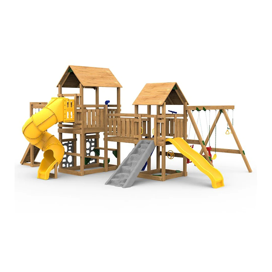
- Page 5 CONTENTS – Gold Design Option Contents: 1 Small Tower Assembly 2 Play Handles 1 large Tower Assembly 2 Sandbox Seats Picnic Table Front View 1 Small Roof Assembly (7 Bds Ea Sd) 2 Play Handles 2 large Roof Assemblies (7 Bds Ea) 1 Bridge Floor Assembly 2 Bridge Rail Assemblies 1 monkey Ring Base Assembly (4 Rocks)
- Page 6 CONTENTS – Silver Design Option Contents: 1 Small Tower Assembly 2 Sandbox Seats 1 large Tower Assembly 2 Play Handles Front View Picnic Table 2 Roof Assemblies (7 Bds Ea Side) 2 Play Handles 2 monkey Ring Beam Assemblies 1 Swing Beam (10' Left w/ Air Rider Brackets) 1 2"...
-
Page 7: Table Of Contents
CONTENTS – Bronze Design Option Contents: 1 Front Tower Assembly 1 Back Tower Assembly 2 Sandbox Seats Picnic Table Front View 1 Roof Assembly (4 Bds Ea Side) 2 Play Handles 1 Roof Assembly (7 Bds Ea Side) 2 monkey Ring Beam Assemblies 1 Swing Beam (8' Left) 1 2"... - Page 8 SMALL TOWER - GOLD STeP 1: Items for (1) Small Tower Assembly (1) 2" x 6" x 82¹ ₄" board (1) 2" x 6" x 72¹ ₂" board (2) ³⁄₈" x 3" lag screws (2) ³⁄₈" washers (20) #8 x 2¹⁄₂" deck screws Lay the tower on its side as shown.
- Page 9 LARGE TOWER - GOLD STeP 3: Items for Fig. 2 Fig. 1 (2) Large Roof Assemblies (2) Roof Caps (4) #8 x 2¹⁄₂" deck screws (12) #14 x 1¹ ₄" pan head screws Position roof assemblies as shown twelve #14 x 1¹ ₄" pan head screws. (Fig.1) keeping square.
- Page 10 BRIDGE ASSEMBLY - GOLD STeP 5: Items for Lift both towers upright and position in final location as shown. Remove the outermost 5/4" x 6" x 18³⁄₄" boards of the Bridge Floor Assembly. (Fig. 1) (1) Bridge Floor Assembly (16) #8 x 2¹⁄₂" deck screws Connect Towers with Bridge Floor Assembly at dimensions shown.
- Page 11 STeP 7: Items for (2) 2" x 4" x 60" boards (16) #8 x 2¹⁄₂" deck screws Position 2" x 4" x 60" boards at dimensions shown. Secure with #8 x 2¹⁄₂" deck screws. 80¹ ₂" Details of Screw Placement Predrill –...
-
Page 12: Front Tower Assembly
FRONT TOWER ASSEMBLY - SILVER STeP 1: Items for (1) Front Tower Assembly (1) 2" x 6" x 82¹ ₄" board (1) 2" x 6" x 72¹ ₂" board (2) ³⁄₈" x 3" lag screws (2) ³⁄₈" washers (20) #8 x 2¹⁄₂" deck screws Lay the tower on its side as shown. -
Page 13: Back Tower Assembly
STeP 2 Items for Position roof assembly so both sides of roof overhang 4" x 4" boards equally. Secure each corner with two #8 x 2¹⁄₂" deck screws and one ³ ₈" x 3" lag screw (1) Roof Assembly with ³ ₈" washer. (See below for detail of screw placement.) (4) ³... -
Page 14: Monkey Ring Beam Assemblies
MONKEY RINGS ASSEMBLY - SILVER STeP 4: Items for (2) Monkey Ring Beam Assemblies (2) 2" x 4" x 28³⁄₈" (4) ³ ₈" x 3" lag screws (4) ³ ₈" washers (16) #8 x 2¹⁄₂" deck screws Position Towers approximately six feet apart as shown. Attach 2"... - Page 15 FRONT TOWER ASSEMBLY - BRONZE STeP 1 Items for (1) Front Tower Assembly (1) Roof Assembly (4) ³ ₈" x 3" lag screws (4) ³ ₈" washers (8) #8 x 2¹⁄₂" deck screws Position roof assembly so both sides of roof overhang 4"...
- Page 16 BACK TOWER ASSEMBLY - BRONZE STeP 2 Items for (1) Back Tower Assembly (1) Roof Assembly (4) ³ ₈" x 3" lag screws (4) ³ ₈" washers (8) #8 x 2¹⁄₂" deck screws Position roof assembly so both sides of roof overhang 4"...
-
Page 17: Swing Beam (8' Left)
SWING BEAM STeP 1: Items for (1) 2" x 6" x 65¹⁄₄" board (1) Left-hand Sturdy-Frame Connector (1) Right-hand Sturdy-Frame Connector (4) #14 x 1¹⁄₄" pan head screws Right Position one Left-hand (L) Sturdy-Frame Connector and one Right-hand (R) Sturdy-Frame Connector as shown. Use Connector as a drill guide and drill ¹⁄₈"... - Page 18 Items for STEP 3: (1) Laminated Swing Beam with Brackets (1) A-Frame Assembly (1) Sturdy-Frame Brace (1) 4" x 4" x 96" (7) ³ " x 4" hex bolts (14) ³ washers (7) ³ " lock nuts Lay swing beam on saw horses with the single bracket pointing down as shown.
- Page 19 Position the single 4" x 4" post under the single bracket so that the holes of the bracket line up with the holes in the single post. Secure with ³⁄₈" x 4" hex bolts, ³⁄₈" washers and ³⁄₈" lock nuts as shown.
- Page 20 STeP 4: Items for (1) Swing Beam Assembly Shown without roof for easier viewing. (1) ³ ₈" x 6" hex bolt (2) ³ ₈" washers (1) ³ ₈" lock nut Lift Swing Beam Assembly to an upright position and attach to the 4' Tower using ³...
- Page 21 ANCHORING At locations shown screw Playset Anchors into ground by hand (a long screwdriver will help). Use the anchor as a drill guide and drill a ¹⁄₄" hole 2¹⁄₂" deep into the board. Attach with ³ ₈" x 3" lag screw and ³ ₈" washer. When anchoring at tower locations, back out existing ³...
- Page 22 Silver Option Bronze Option...
-
Page 23: Giant Scoop Wave Slide
SLIDE – Mounting Instructions Scoop Slide - PS 8813 Scoop Wave Slide - PS 8814 Giant Scoop Wave Slide - PS 8816 1. Align Slide at right angle (90˚) to 48" play deck. Lip of 5. Reinstall Slide permanently, attaching it to play deck Slide should rest on the play deck 1¹... - Page 24 CLIMBING WALL – Assembly Instructions 1. Align top of Climbing Wall at right angle (90˚). Lip of 5. Reinstall Climbing Wall permanently, attaching it to climbing wall should rest on the play deck 1¹ ₂". Using play deck using #14 x 1¹ ₄" pan head screws provided. the Climbing Wall as a template, mark play deck ¹⁄₈"...
- Page 25 CLIMBING STEPS – Assembly Instructions Install the Climbing Steps Assembly to your tower: Position the Climbing Steps Assembly into the 21¹⁄₂" (Bronze) or 16" (Gold) opening of your play deck so that the top surface of the top step is flush with the top surface of the play deck.
-
Page 26: Megascope
USE THE INSTALLATION INSTRUCTIONS AND MOUNTING HARDWARE WHICH ARE SUPPLIED WITH THE FOLLOWING COMPONENTS AIR RIDeR SPIRAl TuBe SlIDe (PS 7958) (PS 8820) COmmeRCIAl GRADe TRAPeZe BAR (PS 7538) SPeAk & SPY meGASCOPe (PS 7838) COMPONENTS - Mounting Instructions SWInG SeAT • GYm RInGS Swing Chain Spacing: 1. - Page 27 COmmeRCIAl GRADe TRAPeZe BAR 1. Hook uncoated ends of chain onto Commercial Grade Swing Hangers Adjustment using Quick-Link Connectors included with PS 7576 (purchased separately). Zone Tighten securely with an adjustable wrench. 2. Using Quick-Link Connectors, attach the Trapeze Bar and one-link chains onto coated ends of Gym Ring chains.
- Page 28 PlayStar, Incorporated, Janesville, WI 53547 © 2010, PlayStar, Inc. Reproduction of this document in part or whole is prohibited without the permission of PlayStar, Inc. Protected by one or more of the following United States or Foreign Patents: US D418,189; US D409,708; US D424,154; US D428,637; US 6,402,663; US D422,332; US D410,059;...
Need help?
Do you have a question about the Super Star XP Gold and is the answer not in the manual?
Questions and answers