
Subscribe to Our Youtube Channel
Related Manuals for PLAYSTAR FACTORY BUILT ALL PRO PS 73831


Summary of Contents for PLAYSTAR FACTORY BUILT ALL PRO PS 73831
- Page 1 ® ® Safety Guide & Assembly Instructions PS 73831 PS 73832 PS 73833 PS 73834 We’re Here To Help! 1-888-752-9782 Call Toll Free Customer Service: Monday - Friday, 8:00 to 5:00 C.S.T. A.M. P.M.
- Page 2 • Thoroughly read all safety instructions before Testing and Materials (ASTM) Home Playground beginning. Safety Standard. In order for PlayStar to comply with the ASTM Standard, we cannot recommend • Children must remain clear of construction site until anyone above these limits.
- Page 3 SAFETY INSTALLATION: seat or single planned activity should The chains or ropes provided are the be allowed on this set at one time, with maximum length designed for the swinging a maximum weight of 105 pounds for 1. Follow the instructions provided, do not element(s).
- Page 4 TOOLS REQUIRED Level 1/8”, 1/4”, & 3/8” Drill Bits (Included) Screwdriver (regular or phillips) Shovel Square Phillips & Slotted Bits (Included) Tape Measure Ladder Pencil Safety Glasses Hack Saw Socket Wrench Hammer 1/2” & 9/16” Sockets Sawhorses (optional) Metal File Drill Adjustable Wrench HARDWARE INCLUDED (shown actual size)
- Page 5 CONTENTS – Gold Design Option Contents: Tower - With: Play Handles Climbing Bars Sand Box Seat Front View Roof Panels (1 w/9 & 1 w/11 Boards) Bridge-Tunnel Assembly With: 2 Play Handles Tunnel (Green) Wood Rock Wall (4 Rocks) Laminated Leg Swing Beam (10’...
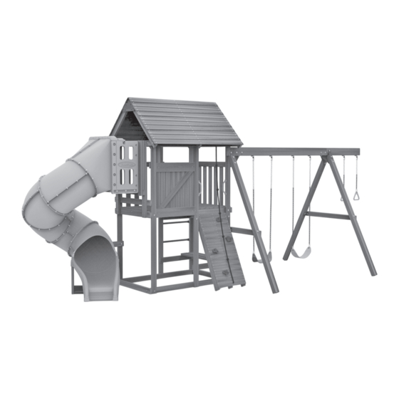
- Page 6 CONTENTS – Silver Design Option Contents: Front View Tower - With: Play Handles Climbing Bars Roof Panels (1 w/9 & 1 w/11 Boards) Wood Rock Wall (4 Rocks) Laminated Leg Swing Beam (10’ Left) A-Frame 2” X 4” X 50 3/4” boards 2”...
- Page 7 CONTENTS – Bronze Design Option Contents: Tower - With: Play Handles Climbing Bars Sand Box Seat Front View Roof Panels (1 w/9 & 1 w/11 Boards) Bridge-Tunnel Assembly With: 2 Play Handles Tunnel (Green) Wood Rock Wall (4 Boards) Laminated Leg Swing Beam (10’...
- Page 8 CONTENTS – Starter Design Option Contents: Front View Tower - With: Play Handles Climbing Bars Roof Panels (1 w/9 & 1 w/11 Boards) Wood Rock Wall (4 Rocks) Laminated Leg Swing Beam (10’ Left) A-Frame 2” X 4” X 50 3/4” boards 2”...
- Page 9 TOWER ASSEMBLY Items for STEP 1: (1) Tower Assembly (1) 2” x 4” x 50C|v” board (4) #8 x 2¹⁄₂” deck screws Position Tower in its desired location. Attach one 2” x 4” x 50C|v” board as shown. Secure with #8 x 2¹⁄₂”...
- Page 10 Items for STEP 2: Attach one 2” x 4” x 50C⁄v” board as shown. Secure with eight #8 x 2¹⁄₂” deck screws from the inside and four from (1) 2” x 4” x 50C|v” board the outside as shown. (12) #8 x 2¹⁄₂” deck screws (Tube Slide opening shown) Flush...
- Page 11 Items for STEP 4: (1) Swing Beam (1) A-frame Assembly Fig. 1 (1) Sturdy-Frame Brace (5) C|₈” x 3¹|₂” hex bolts (10) C|₈” washers (5) C|₈” lock nuts Fig. 2 Lay swing beam on saw horses as shown. (Fig. 1) Position the A-frame assembly so that the top post is above the top bracket and the bottom post is below the bottom bracket.
- Page 12 Step 4 Cont.: Fig. 3 Make sure brace is square to beam. Using the brace as a template, drill a C⁄₈” hole completely through beam. (Fig. 3) Secure the Sturdy-Frame Brace to the beam with a C⁄₈” x 3½” hex bolt, C|₈” washer and C|₈” lock nut. Drill STEP 5: Items for...
- Page 13 Items for STEP 6: Position the laminated leg on the single bracket so that the holes of the bracket line up with the holes in the single post as shown. (1) Laminated Leg (2) C|₈” x 3¹|₂” hex bolts Secure with C|₈” x 3¹|₂” hex bolts, C|₈” washers and C|₈” lock nuts as shown. (4) C|₈”...
- Page 14 Items for STEP 7: Position 2” x 4” x 28” board approximately 34C|v” up from bottom of tower flush with the tower and swing beam posts as shown. Attach with (1) 2” x 4” x 28” board #8 x 2¹|₂” deck screws. (2) Corner brackets Attach corner brackets.
- Page 15 GOLD & BRONZE ONLY Items for STEP 1: Rock Wall Assembly Bridge-Tunnel assembly C⁄₈” x 2” hex bolts C⁄₈” washers C⁄₈” lock nuts Position Rock Wall and Bridge-Tunnel as shown, making sure the C⁄₈” holes line up with the pre-drilled holes. Secure bridge brackets with C⁄₈”...
- Page 16 Items for STEP 2: Bridge-Tunnel Assembly #8 x 2¹⁄₂” deck screws Attach Bridge-Tunnel assem- Flush bly to tower as shown. Make both decks sure its decking frame firmly rests against the tower deck- ing frame without any gap in between. Also, make sure the top surfaces of both decks are flush as shown.
- Page 17 Items for STEP 3: (1) Tunnel (36) #8 x B|₈” truss head screws Position the tunnel into the bridge opening as shown. Make sure the tunnel is fully inserted and the flanges are firmly resting against the lumber and the ends are flush with the sides of the lumber as shown.
- Page 18 SILVER & STARTER ONLY Items for STEP 1: (1) Rock Wall Assembly Attach Rock Wall to corner brackets. Bottom corners of Rock Wall must (4) #8 x 1¹|v” deck screws rest on the ground and the top edge of the Rock Wall must be tight (2) C|₈”...
- Page 19 This Page Left Blank Intentionally.
- Page 20 Drill this hole for roof boards C⁄v” or thinner TAPE HERE TO ROOF...
- Page 21 Dormer Template (cut out) used in Step 1 on Page 24. Drill this hole for roof boards C⁄v” or thinner TAPE HERE TO ROOF...
- Page 22 This Page Left Blank Intentionally.
- Page 23 ROOF ASSEMBLY Items for STEP 1: (1) Roof side left (1) Roof side right (1) Roof cap (6) #14 x 1¹|v” pan head screws On a flat surface position roof sides together as shown. Position roof cap tight against boards as shown. Use roof cap as drill guide and drill ¹|₈”...
- Page 24 Items for STEP 3: (1) Roof Cap (6) #14 x 1¹|v” pan head screws Turn roof over as shown. Position Roof Cap tight against 90º boards as shown. Use Roof Cap as drill guide and drill ¹|₈” holes 1” deep. Keep boards square while attaching Roof Cap to boards with #14 x 1¹|v”...
- Page 25 Items for STEP 4: Position Roof Assembly on tower so that the 1” x 4” x 65¹⁄₂” boards are firmly resting on the 2” x 4” x 50C⁄v” boards. Make sure the roof is level (1) Roof Assembly with the tower and with equal overhang. Allow 1” on all four corners. (4) C⁄₈”...
- Page 26 ANCHORING STARTER & BRONZE DESIGN Items for STEP 1: At locations shown screw Playset Anchors into ground by hand (a long screwdriver will help). (6) Playset Anchors (6) C|₈” x 1¹|₂” lag screws Use the anchor as a drill guide and drill a ¹⁄v” hole 1” deep into the board. (6) C|₈”...
- Page 27 ANCHORING SILVER & GOLD DESIGN Items for STEP 1: At locations shown screw Playset Anchors into ground by hand (a long screwdriver will help). (7) Playset Anchors (7) C|₈” x 1¹|₂” lag screws Use the anchor as a drill guide and drill a ¹⁄v” hole 1” deep into the board. (7) C|₈”...
- Page 28 ACCENT DORMER ATTACHMENT STEP 1 Items for (1) Dormer Template (Pg. 19-22) (4) #8 x 1¹⁄₂” deck screws Set Accent Dormer at the desired location on the roof, making sure it is level. Mark edges with a pencil as shown. Fig. 1 Mark Edges Fig.
- Page 29 This Page Left Intentionally Blank.
- Page 30 Cupola Template (cut out) used in Step 1 on Next Page.
- Page 31 COUNTRY CUPOLA ATTACHMENT STEP 1 Set cupola at the desired location. Mark all six edges as shown. Fig. 1 Items for (1) Cupola Template (Pg. 29-30) Remove cupola. Cut out cupola template. Tape template on the roof, lining up the (1) Cupola Assembly pencil edges.
- Page 32 DECORATE-A-FLAG ATTACHMENT STEP 1 Items for (1) Flag (1) Flag Pole (1) Zip Tie Y o u r d Insert flag onto the flag pole with sewn edge on top as e s i g n g o e s h shown.
- Page 33 FLOWER BOX ATTACHMENT STEP 1 Items for Remove the 1” x 6” x 21¹⁄₂” board from the front of Flower Box (1) Flower Box as shown. Save the #8 x 1¹⁄₂” deck screws. Remove board STEP 2 Items for Set Flower Box at desired location. Using the pre-drilled holes as a guide, predrill (3) #8 x 2¹⁄₂”...
- Page 34 STEP 3 Items for (1) 1” x 6” x 21¹⁄₂” board (from step 1) Re-attach the 1” x 6” x 21¹⁄₂” board to the (5) #8 x 1¹⁄₂” deck screws (from step 1) front of Flower Box as shown. Re-attach board STENCIL SET INSTRUCTIONS 1.
- Page 35 SUNLIGHT WINDOW ATTACHMENT STEP 1 Items for For window openings of approximately 20C⁄v” wide, use a straight edge and fold on the scoring lines at 90º angle as shown. Fig. 1 (1) Sunlight Window (16) #8 x B⁄₈” truss head screws Fold Fig.
- Page 36 DESIGN-A-PLAQUE STEP 1 Items for (1) Design-a-Plaque (4) #8 x 1” truss head screws Plaque can be installed horizontal or diagonal. Position plaque at desired location. Secure with #8 x 1” truss head screws. Y o u r d e s i g n g o e s h e r e Shown Diagonal...
- Page 37 MAGNETIC CHALKBOARD STEP 1 Items for Chalkboard can be installed horizontal or vertical. Position chalkboard at (1) Magnetic Chalkboard desired location. Secure with #8 x B⁄₈” truss head screws. (4) #8 x B⁄₈” truss head screws Caution: To eliminate finger or head entrapments, all gaps around chalkboard - or to the nearest object - must meet the...
- Page 38 SCOOP SLIDE – Mounting Instructions SCOOP SLIDE - PS 8813 1. Align Slide at right angle (90˚) to 60” play deck. Lip of Slide should rest on the play deck 1¹|₂”. Using the Slide as a template, mark play deck through the three holes in the Slide.
- Page 39 COMPONENTS – Mounting Instructions SWING SEAT • GYM RINGS 1. Attach coated ends of chains onto play component using Quick-Link Connectors provided. Tighten securely with Adjustment Zone an adjustable wrench. 2. Hook uncoated ends of chain onto Swing Hangers provided. Swing Chain Spacing: 3.
- Page 40 Thank you for choosing PlayStar. Because it is our intention to make this a positive family experience, we have taken great care in preparing this product. Do not return to the store. Should you have any questions, or if we can assist you in any way, please call our friendly Customer Service Department for immediate action.
Need help?
Do you have a question about the FACTORY BUILT ALL PRO PS 73831 and is the answer not in the manual?
Questions and answers