Table of Contents
Advertisement
Quick Links
Advertisement
Table of Contents

Subscribe to Our Youtube Channel
Related Manuals for IWAKI PUMPS APN-450


Summary of Contents for IWAKI PUMPS APN-450
- Page 1 IWAKI Air Pump APN-450 Instruction Manual Read this manual before use of product...
-
Page 2: Table Of Contents
Thank you for selecting an Iwaki APN-450 Air Pump. This instruction manual deals with "Safety instructions", "Outline", "Installation", "Operation" and "Maintenance" sections. Please read through this manual carefully to ensure the optimum performance, safety and serv- ice of your pump. -
Page 3: Safety Instructions
Safety instructions For the Safe and Correct Handling of the Pump ● "Safety Instruction" section deals with important details about handling of the product. Before use, read this section carefully for the prevention of personal injury or property damage. ● Observe the instructions accompanied with "WARNING" or "CAUTION" in this manual. These instructions are very important for protecting users from dangerous situations. - Page 4 Safety instructions WARNING ● Turn off power Risk of electrical shock. Dismantling/assembling the pump unit without turn- ing off power may cause an electrical shock. Before engaging in any mainte- nance or inspection work, be sure to turn off the pump and related devices. Electrical shock ●...
- Page 5 Safety instructions CAUTION ● Do not wet the pump If a liquid spills over electric parts or wires, a fire or electrical shock may result. Install the pump in a place free from liquid spillage. Prohibited ● Damaged pumps Do not use any damaged pump. Using a damaged pump may lead to an electric leak or shock.
-
Page 6: Outline
Outline 1. Unpacking & Inspection ......5 2. Product outline ........5 3. Specification ......... 6 4. Dimensions ........... 7 5. Performance curves ......9 6. Overview ..........10 7. Exploded view ........11 - 4 -... -
Page 7: Unpacking & Inspection
Discharge pressure Vacuum 2. Check for transit damage and loose bolts. Manufacturing No. 2. Product outline The APN-450 is a diaphragm type air pump. ■ Principle of operation Discharge Suction The rotary motion of the motor is converted through a connecting rod to the reciprocation of the diaphragm in the pump chamber, where gas is transferred from the inlet to outlet. -
Page 8: Specification
■ Pump 50/60Hz Max. dis- Connection I.D. Lowest starting Model Max. air flow charge pres- Max. vacuum Weight temperature Tube Thread sure 12kg 50/60 APN-450 L/min 14.2kg 13.33kPa 0.1MPa [abs.] 12.8kg 100/110 APN-P450 ø12 Rc1/4 0ºC L/min 17.1kg 13.0kg 50/60 3.33kPa... -
Page 9: Dimensions
Outline 4. Dimensions ■ Aluminium pump head type APN-450 (Single head type) 4-M5 Depth 10 APN-P450 (Twin parallel heads type) 4-M5 Depth 10 APN-S450 (Twin series heads type) 4-M5 Depth 10 - 7 -... - Page 10 Outline ■ Corrosive resistant stainless steel pump head APN-450 (Single head type) 4-M5 Depth 10 APN-P450 (Twin parallel heads type) 4-M5 Depth 10 APN-S450 (Twin series heads type) 4-M5 Depth 10 - 8 -...
-
Page 11: Performance Curves
Outline 5. Performance curves ■ APN-450 (Single head type) Vacuum 48.0kPa abs (360 Torr) Vacuum 61.3kPa abs (460 Torr) Vacuum 74.6kPa abs (560 Torr) Vacuum 88.0kPa abs (660 Torr) Vacuum 101.3kPa abs (760 Torr) Air flow L/min ■ APN-P450 (Twin parallel heads type) Vacuum 48.0kPa abs (360 Torr) -
Page 12: Overview
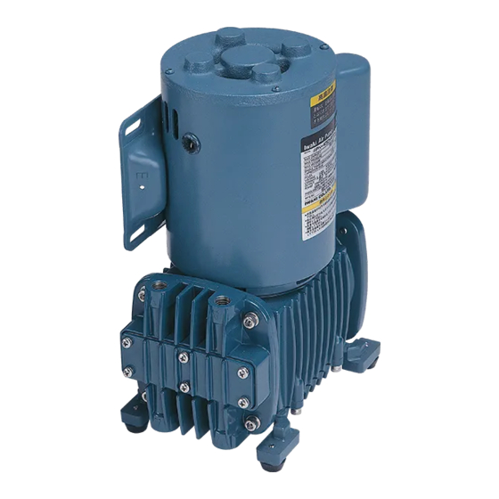
Outline 6. Overview The illustration below shows an APN-450 twin head type. Specification label Use the pump according to the specifications on the label. Power cable Connect to corresponding termi- nals through crimp connectors. Base Be sure to anchor the pump through the bases. -
Page 13: Exploded View
Outline 7. Exploded view ■ APN-450NAT/NATX See this exploded view when dismantling/assembling the pump. Do not dismantle the pump beyond the extent of the instructions on page 28-31, "Wear parts replacement". Connecting rod unit Part names Q'ty No. Part names Q'ty No. - Page 14 Outline ■ APN-P/-S450NAT/NATX See this exploded view when dismantling/assembling the pump. Do not dismantle the pump beyond the extent of the instructions on page 28-31, "Wear parts replacement". Connecting rod unit Part names Q'ty No. Part names Q'ty No. Part names Q'ty Pump head Base...
- Page 15 Outline ■ APN-450NST/NSTX See this exploded view when dismantling/assembling the pump. Do not dismantle the pump beyond the extent of the instructions on page 28-31, "Wear parts replacement". Connecting rod unit Part names Q'ty No. Part names Q'ty No. Part names Q'ty Pump head Gasket...
- Page 16 Outline ■ APN-P/-S450NST/NSTX See this exploded view when dismantling/assembling the pump. Do not dismantle the pump beyond the extent of the instructions on page 28-31, "Wear parts replacement". Part names Q'ty No. Part names Q'ty No. Part names Q'ty Pump head Valve restraint Hex.
-
Page 17: Installation
Installation 1. Before installation ....... 16 2. Installation/Tubing/Electrical wiring ..19 - 15 -... -
Page 18: Before Installation
Installation 1. Before installation Read through instructions in this section to ensure the optimum performance, safety and service of your pump. WARNING ● Do not place dangerous or flammable goods near the pump for your safety. ● Risk of an electrical leak or shock. Do not use a damaged pump. Prohibited ■... - Page 19 Installation ● Do not install the pump in a corrosive or flamma- ble gas atmosphere. Keep good ventilation in a working area. Ambient temperature should not fall below 0°C or exceed 40°C. Observe the allow- able gas temperature range of 0 and 40°C. ●...
- Page 20 Installation ● If the compressed air (higher pressure than atmospheric pressure) is transferred to the pump, sharp deterioration to the lives of the valves, diaphragm and bearing may result. Always keep atmospheric or lower pressure in the suction line. Do not use compressed air. ●...
-
Page 21: Installation/Tubing/Electrical Wiring
Installation 2. Installation/Tubing/Electrical wiring WARNING ● On sensing danger or abnormality, suspend operation immediately and inspect/ solve problems. Caution ■ Installation 1. Ambient temperature around the pump should not exceed 40°C. Observe the allowable maxi- mum ambient humidity of 90%RH. This product is designed for indoor use only. - Page 22 Installation ■ Tubing 1. Tube should be thick enough. The use of a thin and light tube may reduce suction force and an air flow. CAUTION Avoid sharp turns or bends. Otherwise, an tube end may break. 2. The short tubing with the minimum bends is opti- mal to reduce resistance.
- Page 23 Installation ■ Electrical wiring Electrical wiring must be done by a qualified person who has a full knowledge of safety. We are not respon- sible for personal injury or property damage due to nonobservance of this warning. Contact us or your near- est distributor as necessary.
-
Page 24: Operation
Operation 1. Before operation ......... 23 2. Pump operation ........23 - 22 -... -
Page 25: Before Operation
Operation 1. Before operation 1. Before pump operation, check that each tube connection is secured. 2. Check that a suction line is connected to the inlet and a discharge line to the outlet. CAUTION If a suction line and a discharge line are connected the other way around, pumping process is inverted. - Page 26 Maintenance 1. Troubleshooting ........25 2. Maintenance & Inspection....26 3. Wear part replacement ....... 27 - 24 -...
-
Page 27: Maintenance 1. Troubleshooting
Maintenance 1. Troubleshooting Turn off power to stop operation upon sensing abnormalities. And then look for a root cause or contact us as necessary. States Possible causes Solutions The pump is not powered. Check wiring. Motor failure Replace with a new motor. Contact us. Plumbing damage or poor connection Repair plumbing as necessary, or secure connection. -
Page 28: Maintenance & Inspection
Maintenance 2. Maintenance & Inspection ■ Daily inspection Pay attention to the following items during operation. Stop operation on sensing danger and solve problems on the Troubleshooting section. States Points to be checked How to check ● If air is pumped. ●... -
Page 29: Wear Part Replacement
Maintenance 3. Wear part replacement CAUTION ● Turn off power before work Risk of electrical shock. Be sure to turn off power to stop the pump and related devices before work. ● Do not touch the pump or pipe with bare bands Risk of burning. - Page 30 Maintenance ■ Corrosion resistant (stainless) type <APN-450NAT/NATX, APN-P/-S450NAT/NATX> Go through the following steps to take apart or put together the pump. Do not dismantle the pump beyond the extent of the instructions. Diaphragm & seat dismantlement Hexagon socket head bolt 1.
- Page 31 Maintenance Valve replacement 1. Remove the pump head. 2. Remove all the cover mounting screws to take out the valve restraint and valve. Clean valve insertion areas and sealing surfaces Screw hole on the pump head. Sealing surface 3. Take out the valve beneath the pump head as well.
- Page 32 Maintenance ■ Corrosion resistant (stainless) type <APN-450NST/NSTX, APN-P/-S450NST/NSTX> Go through the following steps to take apart or put together the pump. Do not dismantle the pump beyond the extent of the instructions. Diaphragm & seat dismantlement 1. Lay the pump on its side with the pump head upwards.
- Page 33 Maintenance Valve replacement 1. Remove the pump head. 2. Remove the 4 hexagon socket head bolts on the cover with a 4mm wrench to remove valve retain- ers and valves. Clean valve insertion areas and sealing surfaces on the pump head. Screw hole 3.
- Page 34 - 32 -...
- Page 35 - 33 -...
- Page 36 IWAKI Norge AS TEL : (47)23 38 49 00 FAX : 23 38 49 01 China IWAKI Pumps (Guangdong) Co., Ltd. TEL : (86)750 3866228 FAX : 750 3866278 Singapore IWAKI Singapore Pte. Ltd. TEL : (65)6316 2028 FAX : 6316 3221 China GFTZ IWAKI Engineering &...
Need help?
Do you have a question about the APN-450 and is the answer not in the manual?
Questions and answers