Table of Contents
Advertisement
Operating Manual
Translation of the original operating manual
FP (E3.1)
Drying and heating ovens
Avantgarde.Line
with forced convection and program functions
with microprocessor temperature controller
Model
FP 56 (E3.1)
FP 115 (E3.1)
FP 260 (E3.1)
FP 720 (E3.1)
FP 056-UL (E3.1)
FP 115-UL (E3.1)
FP 260-UL (E3.1)
FP 720-UL (E3.1)
BINDER GmbH
Address: Post office box 102, 78502 Tuttlingen, Germany Phone: +49 7462 2005 0
Fax: +49 7462 2005 100 Internet: http://www.binder-world.com
E-mail: info@binder-world.com Service Hotline: +49 7462 2005 555
Service Fax: +49 7462 2005 93 555 Service E-Mail: customerservice@binder-world.com
Service Hotline USA: +1 866 885 9794 or +1 631 224 4340 x3
Service Hotline Asia Pacific: +852 390 705 04 or +852 390 705 03
Service Hotline Russia and CIS: +7 495 988 15 16
Issue 12/2022
Model version
FP056-230V
FP115-230V
FP260-230V
FP720-400V
FP056-120V
FP115-120V
FP260-240V
FP720-208V
Art. No.
9010-0363, 9110-0363
9010-0364, 9110-0364
9010-0365, 9110-0365
9010-0366, 9110-0366
9010-0367, 9110-0367
9010-0368, 9110-0368
9010-0369, 9110-0369
9010-0370, 9110-0370
Art. No. 7001-0434
Advertisement
Table of Contents
Troubleshooting

Related Manuals for Binder APT.line FP 56


Summary of Contents for Binder APT.line FP 56
- Page 1 Fax: +49 7462 2005 100 Internet: http://www.binder-world.com E-mail: info@binder-world.com Service Hotline: +49 7462 2005 555 Service Fax: +49 7462 2005 93 555 Service E-Mail: customerservice@binder-world.com Service Hotline USA: +1 866 885 9794 or +1 631 224 4340 x3 ...
-
Page 2: Table Of Contents
Content SAFETY ........................5 Personnel Qualification ........................5 Operating manual ..........................5 Legal considerations ........................... 5 1.3.1 Intellectual property ........................6 Structure of the safety instructions ...................... 6 1.4.1 Signal word panel ........................6 1.4.2 Safety alert symbol ........................7 1.4.3 Pictograms .......................... - Page 3 AUTHORIZATION LEVELS AND PASSWORD PROTECTION ......32 Password request ..........................32 Assign and modify a password ......................32 9.2.1 Assign and modify the User password ..................32 9.2.2 Assign and modify the Admin password ................. 33 10. FAILSAFE FUNCTION ..................33 11.
- Page 4 21.1 General information, personnel qualification..................63 21.2 Maintenance intervals, service ......................63 21.3 Simple troubleshooting ........................64 21.4 Sending the chamber back to BINDER GmbH ................. 66 22. DISPOSAL......................66 22.1 Disposal of the transport packing ...................... 66 22.2 Decommissioning ..........................66 22.3 Disposal of the chamber in the Federal Republic of Germany ............
-
Page 5: Safety
In no event shall BINDER be held liable for any damages, direct or incidental arising out of or related to the use of this manual. -
Page 6: Intellectual Property
35 U.S.C. § 287(a). Products and services listed on the BINDER website may be sold individually or as part of a combination product. Additional patent applications may also be pending in the U.S. -
Page 7: Safety Alert Symbol
NOTICE Indicates a potentially hazardous situation which, if not avoided, may result in damage to the product and/or its functions or of a property in its proximity. 1.4.2 Safety alert symbol Use of the safety alert symbol indicates a risk of injury. Observe all measures that are marked with the safety alert symbol in order to avoid death or injury. -
Page 8: Word Message Panel Structure
UL chamber: outer chamber door • Figure 1: Position of labels on the chamber front (example: FP 56) Keep safety labels complete and legible. Replace safety labels that are no longer legible. Contact BINDER Service for these replacements. FP (E3.1) 12/2022 page 8/87... -
Page 9: Type Plate
MADE IN GERMANY www.binder-world.com Figure 3: Type plate (example FP-UL 115regular chamber) Indications of the type plate (example) Indication Information BINDER Manufacturer: BINDER GmbH FP 115 Model designation Drying and heating oven Chamber name: Drying and heating oven Serial No. 000000000000... -
Page 10: Ukca Label
(for Germany: DGUV guidelines 213-850 on safe working in laborato- ries, issued by the employers’ liability insurance association). BINDER GmbH is only responsible for the safety features of the chamber provided skilled electricians or qualified personnel authorized by BINDER perform all maintenance and repair, and if components relating to chamber safety are replaced in the event of failure with original spare parts. - Page 11 NOTICE Danger of overheating due to lack of ventilation. Damage to the chamber. ∅ Do NOT install the chamber in unventilated recesses. Ensure sufficient ventilation for dispersal of the heat. Observe the prescribed minimum distances when installing the chamber (chap. 3.4) Do not install or operate the chambers in hazardous locations.
-
Page 12: Intended Use
Such ingredients include in particular acids and halides. Any corrosive damage caused by such ingredients is excluded from liability by BINDER GmbH. The chamber does not dispose of any measures of explosion protection. -
Page 13: Foreseeable Misuse
The requirements described in the Operating Manual for installation site and ambient conditions (chap. 3.4) must be met. WARNING: If customer should use a BINDER chamber running in non-supervised continu- ous operation, we strongly recommend in case of inclusion of irrecoverable specimen or samples to split such specimen or samples and store them in at least two chambers, if this is feasible. -
Page 14: Residual Risks
• Non-compliance with the admissible parameters for processing the respective material. • Installation, testing, service or repair in the presence of solvents • Installation of replacement parts and use of accessories and operating resources not specified and au- thorized by the manufacturer •... - Page 15 • Absence of a plausibility check to rule out erroneous inscription of electrical components • Performance of repair work by untrained/insufficiently qualified personnel • Inappropriate repairs which do not meet the quality standard specified by BINDER • Use of replacement parts other than BINDER original replacement parts •...
-
Page 16: Chamber Description
Chamber description BINDER drying and heating ovens FP are equipped with an Mikroprozessor-Bildschirmregler für Temper- atur und Lüfterdrehzahl, which indicates the temperature with an accuracy of a tenth of a degree. All chambers are heated electrically and ventilated by fan-assisted, forced-air circulation. -
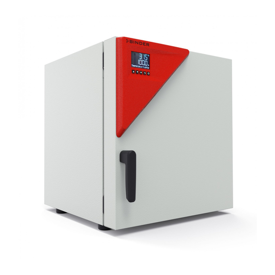
Page 17: Chamber Overview
Chamber overview Figure 5: Overview, closed chamber with single door Figure 6: Overview, open chamber with single door Triangular instrument panel with controller RD4 and USB interface Door handle Outer door On/Off switch (up to size 260) Rack FP (E3.1) 12/2022 page 17/87... -
Page 18: Chamber Rear
Chamber rear (10) Figure 7: Overview, chamber with single door On/Off switch (up to size 260) SUB-D socket “ ” for zero-voltage relay alarm contact and two zero-voltage ALARM SWITCH CONTACT switching contacts SUB-D socket “ ” (option) for optional analog output ANALOG OUTPUT Miniature fuses 250 V AC (T) (up to size 260): 2x 6,3 A for FP 56 und 115, 2x 8 A for FP 260, 2x 12,5 A for FP-UL... -
Page 19: Triangular Instrument Panel
Triangular instrument panel RD4 Controller display Switch for LED Interior lighting (option) USB interface Figure 8: Triangular instrument panel with RD4 chamber controller and USB interface Main power switch (size 720) The chambers size 720 are equipped with a main power (11) switch located on the chamber rear. Figure 9: Main power switch (11) on the chamber rear Zero-voltage switching contacts The chambers are regularly equipped with two zero-voltage switching contacts. -
Page 20: Completeness Of Delivery, Transportation, Storage, And Installation
Note on second-hand chambers (Ex-Demo-Units): Second-hand chambers are chambers that have been used for a short time for tests or exhibitions. They are thoroughly tested before resale. BINDER ensures that the chamber is technically sound and will work flawlessly. Second-hand chambers are marked with a sticker on the chamber door. Please remove the sticker before commissioning the chamber. -
Page 21: Guidelines For Safe Lifting And Transportation
• Permissible ambient temperature range during transport: -10 °C to +60 °C / 14 °F to 140 °F. You can order transport packing and pallets for transportation purposes from BINDER Service. Storage Intermediate storage of the chamber is possible in a closed and dry room. Observe the guidelines for tem- porary decommissioning (chap. - Page 22 Do not install or operate the chamber in potentially explosive areas. DANGER Danger of explosion due to combustible dusts or explosive mixtures in the vicinity of the chamber. Serious injury or death from burns and / or explosion pressure. ∅ Do NOT operate the chamber in potentially explosive areas. ...
-
Page 23: Installation
• Only use original connection cables from BINDER according to the above specification. UL chambers: Use only a UL Listed Power supply cord (UL category ELBZ) according to the above specification. -
Page 24: Connection To An Exhaust/Ventilation System (Optional)
Observe a sufficient current protection according to the number of devices that you want to operate. We • recommend the use of a residual current circuit breaker. Do not place the power cable over the door gap when the chamber is hot after operation. •... -
Page 25: Functional Overview And Menu Structure Of The Rd4 Chamber Controller
You can enter the desired set point values in the “Set points” menu directly at the controller or use the APT-COM™ 4 Multi Management Software (option) specially developed by BINDER. The controller offers various notifications and alarm messages with visual and audible indication. All con- troller settings remain valid until the next manual change. -
Page 26: Menu Structure Of The Controller And Access Levels
• Admin: The password enables access to advanced controller functions and settings. Factory setting is 00 01. • Service: The password enables access to all controller functions (for BINDER Service only). As soon as a password has been assigned, access to the respective functions is blocked and only available after entering the correct password. -
Page 27: Performance During And After Power Failures
To reduce odors quickly we recommend heating up the chamber to its nominal temperature for one day and in a well-ventilated location. WARNING: If customer should use a BINDER chamber running in non-supervised continu- ous operation, we strongly recommend in case of inclusion of irrecoverable specimen or samples to split such specimen or samples and store them in at least two chambers, if this is feasible. -
Page 28: Controller Settings Upon Start Up
WARNING Risk of injury by racks falling down due to overload. Injuries. ∅ Do not exceed the maximum permissible load per rack. ∅ Do not exceed the maximum permissible total load. Gently place the load on the racks. Distribute the load as evenly as possible. Controller settings upon start up Depending on the functions activated in the controller, various settings can be requested directly after turn- ing on the chamber. -
Page 29: Set-Point Entry
Set-point entry Setting ranges Control ranges Temperature 10 °C / 18 °F above ambient temperature up to 0.0 °C / 32 °F up to 330.0 °C / 572 °F 300 ºC / 572 °F Fan speed 40 % up to 100 % Temperature set-point entry Required access level: “User”. -
Page 30: Setting Special Controller Functions
If the air flap is completely open, the spatial temperature accuracy can be negatively influenced. The position of the air flap can be controlled via the controller and the written program. There are the following options: Air flap closed Air flap slightly Air flap half opened Air flap almost Air flap open... - Page 31 The functions are displayed from left to right. Example: Function 1 activated = 1000. Function 1 deactivated = 0000. Submenu “Functions on/off”. This view shows the switching states of the four controller functions. “1” = Function activated “0” = Function deactivated Functions on/off Press the OK button to access the first individual function.
-
Page 32: Authorization Levels And Password Protection
Authorization levels and password protection Password request To access menus for which access is restricted, you must enter the corresponding password. After calling the appropriate menu function with the OK button the password request appears. Password request. The left two digits are flashing. Enter the desired numbers with the ar- row buttons. -
Page 33: Assign And Modify The Admin Password
For information, the alarm message "Sensor defective!" is issued (chap. 14.2), but the chamber continues to function and displays the correct temperature value. Contact BINDER Service to replace the defective sensor. FP (E3.1) 12/2022... -
Page 34: Overtemperature Protection
Overtemperature protection 11.1 Overtemperature protective device class 1 The chambers are regularly equipped with an overtemperature protective device (bimetallic switch) safety device class 1 acc. to DIN 12880:2007. It serves to protect the chamber, its environment and the contents against exceeding the maximum permissible temperature. When a defined cut-off temperature is reached, the overtemperature protective device turns off the heating. -
Page 35: Overtemperature Safety Controller Class 2 / 3.1
11.2 Overtemperature safety controller class 2 / 3.1 The chambers are regularly equipped with an adjustable electronic safety controller. It serves to protect the chamber, its environment and the contents against exceeding the maximum permissible temperature. Please observe the regulations applicable to your country (for Germany: DGUV guidelines 213-850 on safe working in laboratories, issued by the employers’... -
Page 36: Selecting Between Safety Controller Class 2 (Temperature Limiter) Or Class 3.1
11.2.1 Selecting between safety controller class 2 (temperature limiter) or class 3.1 You have the option of operating the safety controller with class 2 or 3.1 functionality. Erforderliche Berechtigung: „Admin“. Path: Normal display Settings Various Protection class Press the OK button to enable the setting. Selecting the class of the safety controller. -
Page 37: Setting The Safety Controller Value
Setting the safety controller mode The current setting flashes. Use the arrow buttons to select between LIMI (Limit) and OFFS (Offset). Confirm the setting with the OK button. Mode With the arrow-down button you proceed to setting the safety controller value (chap. 11.2.4) With the Back button you can go back to the “Safety controller”... -
Page 38: Function Check
• If the inner chamber temperature has already cooled down below the safety controller value when press- ing the OK button, the alarm message “Safety controller” and the “Collective alarm” icon are reset together with the buzzer. • If the state of alarm is still active when pressing the OK button, i.e. the inner chamber temperature is still above the safety controller value, first only the buzzer is reset. -
Page 39: Selecting The Temperature Unit
12.2 Selecting the temperature unit Required access level: “Admin”. Following start-up of the chamber (chap. 6), it is “User”. Path: Normal display Settings Chamber Temperature unit Press the OK button to enable the setting. Setting the temperature unit The current setting flashes. Use the arrow buttons to select between °C (degrees Celsius) and °F (degrees Fahrenheit). -
Page 40: Setting The Current Time
Setting the date: year The right two digits are flashing. Enter the last two digits of the current year with the arrow buttons. Confirm the entry with the OK button. Date With the arrow-down button you can now change to setting the current time. Normal With the Back button you can go back to the “Chamber”... -
Page 41: Setting The Chamber Address
12.6 Setting the chamber address This setting is required for the communication with the BINDER APT-COM™ 4 Multi Management Software. The chamber address settings in the chamber controller and in the software must be identical. Required access level: “Admin”. Path:... -
Page 42: Tolerance Range Settings
Tolerance range settings In this menu you can define the deviation between the actual value and setpoint, which that shall cause a tolerance range alarm. The entered value defines the limit of permitted deviations from the set-point (ex- ceeding and falling below). Reaching this limit triggers tolerance alarm. In addition, you can specify a delay time for this alarm. -
Page 43: Notification And Alarm Functions
Notification and alarm functions 14.1 Information messages Information messages provide information about the settings made or the current controller condition. The message is displayed immediately when the condition occurs. In Normal display a text message indicates the condition. The “Information” icon is flashing slowly. -
Page 44: Activating / Deactivating The Audible Alarm (Alarm Buzzer)
In Normal display a text message indicates the alarm cause. The collective alarm icon flashes. If the audible arm is activated, the buzzer sounds. Press the OK button to confirm the alarm and mute the buzzer. If the alarm cause is still valid, the collective alarm icon is lit. -
Page 45: Zero-Voltage Relay Alarm Contact
Setting the audible alarm. The current setting flashes. Use the arrow buttons to select between ON and OFF. Confirm the setting with the OK button. Audible alarm With the Back button you can go back to the “Chamber” submenu and, repeatedly pressing it, to Normal display. -
Page 46: Program Start / Stop Function
Week programs: Programming is done using the BINDER RD4 Program Editor, which you can download from the BINDER website. The RD4 program editor is a Windows application that can be used to create programs on a PC and transfer them to compatible BINDER chambers via USB memory stick. -
Page 47: Stop Program
Ethernet network settings The settings of this submenu are used for networking chambers with an Ethernet interface, e.g. to connect them with BINDER’s APT-COM™ 4 Multi Management Software (option, chap. 19.1). 16.1 Showing the network settings Required access level: “User”. -
Page 48: Showing The Ip Address
16.1.2 Showing the IP address Path: Normal display Chamber info Ethernet IP address Display of the IP address (example) Toggle forth and back with the Back button and the OK button. 0.0.0.0 IP address With the arrow-down button you can now change to the next parameter (subnet mask). Normal With the Back button you can go back to the “Ethernet”... -
Page 49: Showing The Dns Server Address
16.1.5 Showing the DNS server address Path: Normal display Chamber info Ethernet DNS server address Display of the DNS server address (example) Toggle forth and back with the Back button and the OK button. DNS server address 0.0.0.0 With the arrow-down button you can now change to the next parameter (DNS chamber name). With the Back button you can go back to the “Ethernet”... -
Page 50: Selecting The Type Of Ip Address Assignment (Automatic / Manual)
16.2.1 Selecting the type of IP address assignment (automatic / manual) Path: Normal display Settings Ethernet IP address assignment Press the OK button to enable the setting Selection of the type of assignment of the IP address. The current setting flashes. Use the arrow buttons to select between AUTO (automatic) and MANU (manual). -
Page 51: Setting The Subnet Mask
IP address assignment (sample values). The first section of the IP address is shown. Enter the desired value with the arrow buttons. Use the OK button to confirm the entry and proceed to the second sec- tion of the IP address. IP address IP address assignment (sample values). -
Page 52: Setting The Standard Gateway
16.2.5 Setting the standard gateway Access to this function is possible only if manual IP address assignment has been selected (chap. 16.2.1) Path: Normal display Settings Ethernet Standard gateway Press the OK button to enable the setting. The standard gateway entry is done in four steps, corresponding to the number sections: (1).(2).(3).(4) Principle of entry: •... -
Page 53: Recorded Data
(chap. 17.3). Temperature values are always given out in °C. • Chamber data for BINDER Service “DL2” This data is intended for use by BINDER Service. It also contains information from the self-test function. The storage rate is fix (1 minute). Temperature values are always given out in °C. -
Page 54: Deleting The Data Recorder
For detailed information on the file content see chap. 17.1. • Service data The "Service" folder is created on the USB stick and can be sent to BINDER Service. In addition to the configuration and recorder data, it contains further service-relevant information. -
Page 55: Import Function
18.2 Import function Required access level: “Admin”. Function “Import configuration”. To import configuration data from the USB stick, press the OK button. Import configuration With the arrow-down button you can now change to the setting of the “Export configuration” function. 18.3 Export functions Required access level: any user Function “Export configuration”. -
Page 56: Error During Data Transmission
Options 19.1 APT-COM™ 4 Multi Management Software (option) The chamber is regularly equipped with an Ethernet interface (6) that can connect the BINDER APT-COM™ 4 Multi Management Software. The MAC Address is indicated in the “Ethernet” controller menu (chap. 16.1.1). The actual temperature values are given at adjustable intervals. Programming can be performed graphically via PC. -
Page 57: Analog Output For Temperature (Option)
Technical data of thePt100 sensor: Three-wire technique • Class B (DIN EN 60751) • Temperature range up to 320 °C / 608 °F • Stainless steel protective tube 45 mm length, material no. 1.4501 • 19.3 Analog output for temperature (option) With this option the chamber is equipped with an analog output 4-20 mA for temperature. -
Page 58: Inert Gas Connection With Mostly Gas-Tight Version (Option)
The air flap does not close the exhaust duct completely. The delivered plug serves to avoid emerging of vapors or loss of introduced inert gas, if any, via the exhaust duct. Due to special demands of heat re- sistance, use the delivered plug only. NOTICE Danger of inflammation when using an inappropriate plug. - Page 59 DANGER Risk of suffocation through high concentration of inert gas. Death by suffocation. ∅ Do NOT set up chambers in non-ventilated recesses. Ensure technical ventilation measures. Observe the relevant regulations for handling inert gases. Close the gas supply when decommissioning the chamber. Inert gases, which are heavier than air, may accumulate in low-lying areas of the installation site.
-
Page 60: Cleaning And Decontamination
Do NOT use a neutral cleaning agent on zinc coated surfaces. Do not use cleaning agents that may cause a hazard due to reaction with components of the device or the charging material. If there is doubt regarding the suitability of cleaning products, please contact BINDER service. - Page 61 NOTICE Danger of corrosion by using unsuitable cleaners. Damage to the chamber. ∅ Do NOT use acidic or chlorine cleaning detergents. ∅ Do NOT use a neutral cleaning agent on other kind of surfaces e.g., the zinc coated hinge parts or the rear chamber wall. For surface protection, perform cleaning as quickly as possible.
-
Page 62: Decontamination / Chemical Disinfection
For chemical disinfection, we recommend using the disinfectant spray Art. No. 1002-0022. Any corrosive damage that may arise following use of other disinfectants is excluded from lia- bility by BINDER GmbH. With every decontamination / disinfection method, always use adequate personal safety con- trols. -
Page 63: Maintenance And Service, Troubleshooting, Repair, Testing
For personnel requirements please refer to the Service Manual. • Repair Repair of the chamber can be performed by BINDER Service or by BINDER qualified service partners or technicians, in accordance with the description in the Service Manual. After maintenance, the chamber must be tested prior to resuming operation. -
Page 64: Simple Troubleshooting
If there are is a technical fault or shortcoming, take the chamber out of operation and inform BINDER Service. If you are not sure whether there is a technical fault, proceed ac- cording to the following list. If you cannot clearly identify an error or there is a technical fault, please contact BINDER Service. - Page 65 Chamber operation can be contin- Alarm message “Sensor defec- defective. The Failsafe temper- ued for the time being. Contact tive!”is displayed. ature sensor takes over the BINDER service for sensor replace- measurement. ment. Actual temperature value display Regular temperature and Fail- shows safe temperature sensor de- Contact BINDER service.
-
Page 66: Sending The Chamber Back To Binder Gmbh
21.4 Sending the chamber back to BINDER GmbH If you return a BINDER product to us for repair or any other reason, we will only accept the product upon presentation of an authorization number (RMA number) that has previously been issued to you. An au- thorization number will be issued after receiving your complaint either in writing or by telephone prior to your sending the BINDER product back to us. -
Page 67: Disposal Of The Chamber In The Federal Republic Of Germany
(Elektro- und Elektronikgerätegesetz, ElektroG from 20 October 2015, BGBl. I p. 1739) or contact BINDER service who will organize taking back and disposal of the cham- ber according to the German national law for electrical and electronic equipment (Elektro- und El- ektronikgerätegesetz, ElektroG from 20 October 2015, BGBl. -
Page 68: Disposal Of The Chamber In The Member States Of The Eu Except For The Federal Republic Of Germany
According to Annex I of Directive 2012/19/EU of the European Parliament and of the Council on waste electrical and electronic equipment (WEEE), BINDER devices are classified as “monitoring and control instruments” (category 9) only intended for professional use“. They must not be disposed of at public col- lecting points. -
Page 69: Disposal Of The Chamber In Non-Member States Of The Eu
December 1996 by TÜV CERT). All test equipment used is subject to the administration of measure- ment and test equipment that is also constituent part of the BINDER QM DIN EN ISO 9001 systems. They are controlled and calibrated to a DKD-Standard at regular intervals. -
Page 70: Over Current Protection
Do NOT place samples outside this usable volume. Do NOT load this volume by more than half to enable sufficient airflow inside the chamber. Do NOT divide the usable volume into separate parts with large area samples. Do NOT place samples too close to each other in order to permit circulation between them and thus obtain a homogenous distribution of temperature. - Page 71 +22 °C +/- 3 °C / 71.6 °F +/- 5.4 °F and a power supply voltage fluctuation of +/-10%. Technical data is determined in accordance to BINDER Factory Standard Part 2:2015 and DIN 12880:2007. All indications are average values, typical for chambers produced in series. We reserve the right to change technical specifications at any time.
-
Page 72: Equipment And Options (Extract)
If the chamber is fully loaded, the specified heating up times may vary according to the load. 23.5 Equipment and options (extract) To operate the chamber, use only original BINDER accessories or accessories / components from third-party suppliers authorized by BINDER. The user is responsible for any risk arising from using unauthorized accessories. Standard equipment... -
Page 73: Accessories And Spare Parts (Extract)
23.6 Accessories and spare parts (extract) BINDER GmbH is responsible for the safety features of the chamber only, provided skilled electricians or qualified personnel authorized by BINDER perform all maintenance and repair, and if components relating to chamber safety are replaced in the event of failure with original spare parts. -
Page 74: Dimensions Size 56
23.7 Dimensions size 56 [Dimensions in mm] FP (E3.1) 12/2022 page 74/87... -
Page 75: Dimensions Size 115
23.8 Dimensions size 115 [Dimensions in mm] FP (E3.1) 12/2022 page 75/87... -
Page 76: Dimensions Size 260
23.9 Dimensions size 260 [ Dimensions in mm] FP (E3.1) 12/2022 page 76/87... -
Page 77: Dimensions Size 720
23.10 Dimensions size 720 [ Dimensions in mm] FP (E3.1) 12/2022 page 77/87... -
Page 78: Certificates And Declarations Of Conformity
Certificates and declarations of conformity 24.1 EU Declaration of Conformity FP (E3.1) 12/2022 page 78/87... - Page 79 FP (E3.1) 12/2022 page 79/87...
- Page 80 FP (E3.1) 12/2022 page 80/87...
-
Page 81: Ukca Declaration Of Conformity
24.2 UKCA Declaration of Conformity FP (E3.1) 12/2022 page 81/87... -
Page 82: Contamination Clearance Certificate
Contamination clearance certificate 25.1 For chambers located outside the USA and Canada Declaration with regard to safety and health Erklärung zur Sicherheit und gesundheitlichen Unbedenklichkeit The German Ordinance on Hazardous Substances (GefStofV), and the regulations regarding safety at the workplace, require that this form be filled out for all products that are returned to us, so that the safety and health of our employees can be warranted. - Page 83 Kind of transport / transporter / Transportweg/Spediteur: Transport by (means and name of transport company, etc.) Versendung durch (Name Spediteur o.ä.) ___________________________________________________________________________________ Date of dispatch to BINDER GmbH / Tag der Absendung an BINDER GmbH: ___________________________________________________________________________________ FP (E3.1) 12/2022 page 83/87...
- Page 84 We herewith commit ourselves and guarantee that we will indemnify BINDER GmbH for all damages that are a consequence of incomplete or incorrect information provided by us, and that we will exempt BINDER GmbH from eventual damage claims by third parties./ Wir versichern, dass wir gegenüber BINDER für jeden...
-
Page 85: For Chambers Located In The Usa And Canada
Please complete this form and the Customer Decontamination Declaration (next 2 pages) and attach the required pictures. E-mail to: IDL_SalesOrderProcessing_USA@binder-world.com After we have received and reviewed the complete information we will decide on the issue of a RMA num- ber. Please be aware that size specifications, voltage specifications as well as performance specifications are available on the internet at www.binder-world.us... - Page 86 Customer (End User) Decontamination Declaration Health and Hazard Safety declaration To protect the health of our employees and the safety at the workplace, we require that this form is com- pleted by the user for all products and parts that are returned to us. (Distributors or Service Organizations cannot sign this form) NO RMA number will be issued without a completed form.
- Page 87 4.5 Shipping laws and regulations have not been violated. I hereby commit and guarantee that we will indemnify BINDER Inc. for all damages that are a con- sequence of incomplete or incorrect information provided by us, and that we will indemnify and hold harmless BINDER Inc.
Need help?
Do you have a question about the APT.line FP 56 and is the answer not in the manual?
Questions and answers