Table of Contents
Advertisement
Quick Links
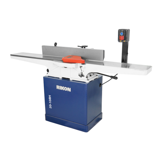
20-108H
8" Jointer
with Helical Cutterhead
Operator's Manual
Record the serial number and date of purchase in your manual for future reference.
Serial Number: _________________________
Date of purchase: _________________________
For technical support or parts questions, email techsupport@rikontools.com or call toll free at (877)884-5167
www.rikontools.com
20-108HM2
Advertisement
Table of Contents

Related Manuals for Rikon Power Tools 20-108H


Summary of Contents for Rikon Power Tools 20-108H
- Page 1 20-108H 8” Jointer with Helical Cutterhead Operator’s Manual Record the serial number and date of purchase in your manual for future reference. Serial Number: _________________________ Date of purchase: _________________________ For technical support or parts questions, email techsupport@rikontools.com or call toll free at (877)884-5167 www.rikontools.com...
-
Page 2: Table Of Contents
Changes and improvements may be made at any time, with no obligation on the part of Rikon Power Tools, Inc. to modify previously delivered units. Reasonable care has been taken to ensure that the information in this manual is correct, to provide you with the guidelines for the proper safety,... -
Page 3: Safety Instructions
SAFETY INSTRUCTIONS IMPORTANT! Safety is the single most important consideration in the operation of this equipment. The following instructions must be followed at all times. Failure to follow all instructions listed below may result in electric shock, fire, and/or serious personal injury. There are certain applications for which this tool was designed. -
Page 4: Knife Insert Size (Lxwxt)
SAFETY INSTRUCTIONS 12. KEEP PROTECTIVE GUARDS IN PLACE AND IN 25. ALWAYS WEAR A DUST MASK TO PREVENT WORKING ORDER. INHALING DANGEROUS DUST OR AIRBORNE PARTICLES, including wood dust, crystalline silica dust 13. AVOID ACCIDENTAL STARTING. Make sure that and asbestos dust. Direct particles away from face and the power switch is in the “OFF”... -
Page 5: Electricals & Wiring Diagram
SAFETY INSTRUCTIONS ELECTRICAL SAFETY EXTENSION CORDS THIS TOOL IS PRE-WIRED FOR 220V THE USE OF AN EXTENSION CORD WITH THIS MACHINE IS NOT RECOMMENDED. For CIRCUITS, AND MUST BE GROUNDED WHILE IN USE TO PROTECT THE OPERATOR FROM ELECTRIC SHOCK. best power and safety, plug the machine directly into a dedicated, grounded electrical outlet that is within the IN THE EVENT OF A MALFUNCTION OR BREAKDOWN,... - Page 6 SAFETY INSTRUCTIONS SPECIFIC SAFETY INSTRUCTIONS FOR JOINTERS This machine is intended for the surfacing of natural, solid woods. The permissible workpiece dimensions must be observed (see Technical Specification). Any other use not as specified, including modification of the machine or use of parts not tested and approved by the equipment manufacturer can cause unforeseen damage and invalidate the warranty.
-
Page 7: Getting To Know Your Machine
PARTS DIAGRAMS AND PARTS LISTS CONTENTS OF PACKAGE Model 20-108H Jointer is shipped in two boxes. Unpacking and Clean-up 1. Carefully remove all contents from the shipping carton. Compare the contents with the list of contents to make sure that all of the items are accounted for, before discarding any packing material. Place parts on a protected surface for easy identification and assembly. -
Page 8: Installation
CONTENTS OF PACKAGE LOOSE PARTS IN CARTON 1 LOOSE PARTS IN CARTON 2 HARDWARE LIST OF LOOSE PARTS A. Jointer Top H. Fence Tilt Handle O. M8 x 20 Allen Bolt (x4) B. Fence I. Fence Mounting Bracket P. M6 x 25 Allen Bolt (x4) C. -
Page 9: Assembly
ASSEMBLY THE MACHINE MUST NOT BE PLUGGED IN AND THE POWER SWITCH MUST BE IN THE 'OFF' POSITION UNTIL ASSEMBLY IS COMPLETE. JOINTER TOP ASSEMBLY 1. Remove rear door of the jointer stand. Four Threaded Holes 2. Place jointer top assembly on top of stand, making sure the pulleys face the rear of the cabinet. - Page 10 ASSEMBLY THE MACHINE MUST NOT BE PLUGGED IN AND THE POWER SWITCH MUST BE IN THE 'OFF' POSITION UNTIL ASSEMBLY IS COMPLETE. DRIVE BELT & PULLEY ALIGNMENT Motor Mounting The procedure below will ensure drive belt longevity Nuts (x4) and reduce vibration. If the pulleys are not set cor- rectly, excess wear to the belts and power transfer may be reduced.
- Page 11 ASSEMBLY INSTALLING THE FENCE THE MACHINE MUST NOT BE PLUGGED IN AND THE POWER SWITCH MUST BE IN CONTINUED FROM PAGE 10 THE OFF POSITION UNTIL ALL ADJUSTMENTS ARE 2. Attach the Fence Mounting Bracket to the rear of COMPLETE. the jointer body by using the four M8 x 45mm Allen bolts.
- Page 12 ASSEMBLY THE MACHINE MUST NOT BE PLUGGED IN AND THE POWER SWITCH MUST BE IN THE OFF POSITION UNTIL ALL ADJUSTMENTS ARE COMPLETE. DUST PORT ASSEMBLY A Dust Port (A) is supplied with the jointer to help connect it to a standard 4 inch vacuum hose. 1.
-
Page 13: Operation
STARTING AND STOPPING JOINTER 1. The 20-108H 8” Jointer is equipped with a safety switch with a “lockout” feature to prevent unintended use. A hole (A-FIG 16 ) is located behind the “ON”... - Page 14 OPERATION CONTINUED FROM PAGE 13 STARTING AND STOPPING JOINTER 2. The ON/OFF switch is located on the front of the jointer. To turn the jointer “ON”, depress (A) the blue round button until a “snap” sound is heard. 3. To turn the jointer “OFF”, depress (B) the red paddle until a “snap”...
- Page 15 OPERATION FEEDING THE WORKPIECE Place the workpiece on top of the right, infeed table. The workpiece will be cut on its underside by the rotating cutterhead knives. When jointing, the feeding direction of the workpiece is right-to-left over the cutterhead. FIG. 19. 1.
-
Page 16: Adjustments
ADJUSTMENTS THE MACHINE MUST NOT BE PLUGGED IN AND THE POWER SWITCH MUST BE IN THE OFF POSITION UNTIL ALL ADJUSTMENTS ARE COMPLETE. FENCE ADJUSTMENTS 1. To move the fence across the table, loosen the lock lever (A), then turn the knob (B) until the fence is in the desired position on the table and then retighten the lock lever. - Page 17 ADJUSTMENTS THE MACHINE MUST NOT BE PLUGGED IN AND THE POWER SWITCH MUST BE IN THE OFF POSITION UNTIL ADJUSTMENTS ARE COMPLETE. ROTATING OR REPLACING KNIFE INSERTS INDEX MARK This machine has a helical cutterhead with four rows of STAR HEAD carbide knife inserts.
- Page 18 ADJUSTMENTS THE MACHINE MUST NOT BE TABLE ADJUSTMENTS PLUGGED IN AND THE POWER SWITCH MUST BE IN THE OFF POSITION UNTIL ALL ADJUSTMENTS ARE The infeed and outfeed tables are preset at the COMPLETE. factory to be aligned with the cutterhead. To ensure that both tables are aligned, check both table settings and adjust as necessary.
- Page 19 ADJUSTMENTS CONTINUED FROM PAGE 18 5. Do the same measurement with the straight edge from the infeed table, to the same insert cutters that Straight Edge were used to measure the outfeed table. 6. Once the infeed and outfeed tables are aligned with the cutterhead, the tables need to be checked Check Clearance to confirm that their surfaces are parallel with each...
-
Page 20: Maintenance
MAINTENANCE Turn the power switch “OFF” and disconnect the plug from the outlet prior to adjusting or maintaining the machine. DO NOT attempt to repair or maintain the electrical components of the motor. Contact a qualified service technician for this type of maintenance. 1. -
Page 21: Troubleshooting
TROUBLESHOOTING FOR YOUR OWN SAFETY, ALWAYS TURN OFF AND UNPLUG THE MACHINE BEFORE CARRYING OUT ANY TROUBLESHOOTING. SYMPTOM POSSIBLE CAUSES SOLUTIONS 1. Check power source, plug and wiring. Machine will not start. 1. No power 2. Check and reset circuit breaker. 2. -
Page 22: Parts Diagrams & Parts Lists
PARTS DIAGRAM... - Page 23 PARTS LIST 20-108H 8” JOINTER TABLE ASSEMBLY PART PART QTY. DESCRIPTION DESCRIPTION QTY. INFEED TABLE P20-108H-1 SET SCREW M8x25 P20-108H-35 SPECIAL WASHER P20-108H-2 NUT M8 P20-108H-36 1/8 PLATE P20-108H-3 P20-108H-37 WASHER 5MM P20-108H-4 CAP SCREW M8x20 P20-108H-38 POINTER P20-108H-5 BLOCK...
- Page 24 PARTS DIAGRAM 20-108H 8” JOINTER CUTTERHEAD PARTS LIST PART QTY. DESCRIPTION CUTTER HEAD P20-108H-201 INDEXABLE INSERT P20-108H-202 FLAT CAP SCREW M5x12 P20-108H-203 L-WRENCH TORX P20-108H-204 DRIVER BIT TORX P20-108H-205 BEARING BLOCK P20-108H-206 STUD P20-108H-207 LOCK WASHER 10MM P20-108H-208 HEX NUT M10...
- Page 25 PARTS DIAGRAM 20-108H 8” JOINTER FENCE PARTS LIST PART PART DESCRIPTION QTY. QTY. DESCRIPTION FENCE P20-108H-301 LOCK SHAFT P20-108H-322 SET SCREW M5x4 P20-108H-302 FENCE RAM SUPPORT P20-108H-323 P20-108H-303 BLOCK FLAT WASHER M8 P20-108H-324 STUD M10 P20-108H-304 FENCE RAM BRACKET P20-108H-325...
- Page 26 PARTS DIAGRAM 20-108H 8” JOINTER BASE PARTS LIST PART PART DESCRIPTION QTY. QTY. DESCRIPTION STAND BASE P20-108H-401 HEX BOLT M8x25 P20-108H-413 STAND BODY P20-108H-402 FENDER WASHER 8MM P20-108H-414 HEX NUT M8 P20-108H-403 HEX BOLT M8x35 P20-108H-415 LOCK WASHER 8MM P20-108H-404...
-
Page 27: Accessories
ACCESSORIES 25-699 Replacement Carbide Inserts - PK 10 4-Sided, pre-sharpened carbide insert knives measure 14mm x 14mm x 2mm (0.55" x 0.55" x 0.078"). Pack of 10. 25-694 Mounting Screws for Inserts - PK 10 Special flat head, T20 Star drive screws for mounting insert cutters onto cutterheads. - Page 28 20-108H For more information: 16 Progress Road Billerica, MA 01821 877-884-5167 / 978-528-5380 techsupport@rikontools.com www.rikontools.com 20-108HM2...
Need help?
Do you have a question about the 20-108H and is the answer not in the manual?
Questions and answers