Table of Contents
Advertisement
The
Challenge
Machinery
Company
provides
owner's
manuals on its products solely as a courtesy to its customers.
See the information below before using this manual.
These manuals are for reference only. These manuals include products which are non-
current, unsupported or no longer produced by The Challenge Machinery Company, and are
provided solely as an accomodation to our customers. By providing these manuals, The
Challenge Machinery Company makes no representation or warranty as to the products,
their current condition, or their suitability or fitness for use in any particular application, which
are the sole and independent responsibility of the product owner and user.
Older products may not comply with current safety procedures, guidelines or regulations,
and it is the product owner's and user's responsibility to evaluate the suitability and fitness of
the products in their current use and application. The Challenge Machinery Company makes
no representation, warranty or recommendation regarding any modifications which may be
required on non-current or unsupported products. The Challenge Machinery Company
assumes no liability for any modification or alteration to any Challenge product, and any such
modification or alteration to any Challenge product is not authorized by The Challenge
Machinery Company. The availability of these manuals is solely for the purpose of providing
reference information for the products.
This
manual may not be
complete
in
all aspects of product
maintenance and repair. All
products should be used only by qualified and properly trained personnel, following proper
safety procedures. All products should be regularly inspected and maintained, and their condition,
application and use should be periodically evaluated by qualified personnel. Only qualified and
properly trained technicians should
perform maintenance, repair and replacement
procedures. Attempting these procedures without proper training may cause machine
damage or operator injury!
Products may be unsupported by The Challenge Machinery Company due to age or the
unavailability of parts from their original manufacturer. No parts or product support will be
available to repair or maintain unsupported products. Older products may not be UL listed (if
the product does not have a UL label it is not a listed product), and may not comply with
applicable installation or other regulations or requirements if relocated to a new facility.
Many municipalities require
a
product to be UL listed before
an electrician
will
connect power
to them. Often the cost of updating an older product to comply with current safety regulations is
greater than the value of the product.
Advertisement
Table of Contents

Related Manuals for Challenge JO


Summary of Contents for Challenge JO
- Page 1 The Challenge Machinery Company assumes no liability for any modification or alteration to any Challenge product, and any such modification or alteration to any Challenge product is not authorized by The Challenge Machinery Company.
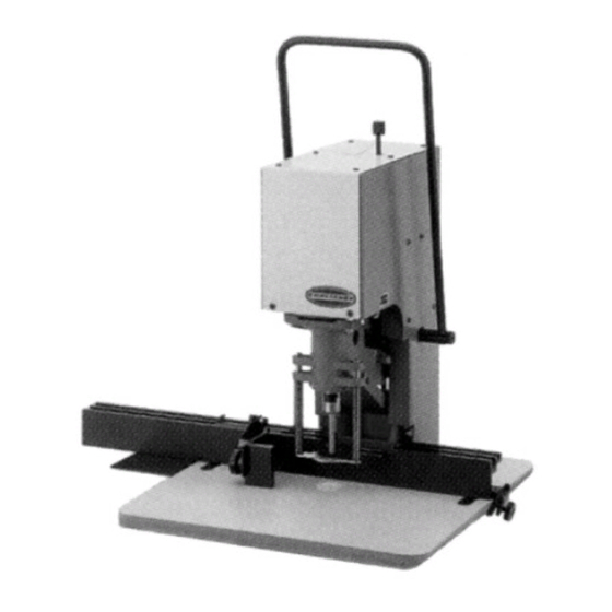
- Page 2 Serial Numbers 74046 & Up NSTRUCTION AND ARTS ANUAL MODEL JO PAPER DRILLING MACHINE Sold and Serviced by The Challenge Machinery Company 6125 Norton Center Drive Norton Shores, MI 49441-6081 USA ChallengeMachinery.com F.393-F JUNE 2003...
-
Page 3: Introduction
DIRECTLY TO CHALLENGE. If you bought a used machine, it is important to have the following information on record at Challenge. Copy this page, fill in the information and send it care of The Challenge Service Department, 6125 Norton Center Drive •... -
Page 4: Table Of Contents
10.3.1 V-Slotting ........................19 10.3.2 Slitting.......................... 21 10.4 Light Duty Cornering Machine – A-6401 ................22 11.0 Accessories for Challenge Paper Drilling Machine ..............25 11.1 Genuine Challenge Hollow Drills..................25 11.2 Challenge Drill-Ease Lubricant Stick ..................26 11.3 Challenge Drilling Blocks..................... 26 11.4 Challenge Fiber Blocks...................... -
Page 5: Safety
If the machine sounds or operates abnormally, turn it off and consult the Trouble Shooting section of this manual. If the problem cannot be corrected, have it checked by a qualified service person or your Authorized Challenge Dealer. • CRUSH HAZARD, keep feet off the pedal when handling paper under the clamp. DO NOT REST FOOT ON PEDAL at any time! •... -
Page 6: Warning Label Definitions
2.0 Safety 2.3 Warning Label Definitions The following warning labels are found at various locations on your machine. Read and understand the meaning of each symbol. If a label is lost from the machine, it should be replaced. The item number and location of each label can be found in Section 10.0 Parts List. -
Page 7: Packing List
3.0 Packing List 3.0 Packing List Part No. Description Qty. Basic Machine 14056 Backgauge Assembly 46022 Table Assembly 46018 Tool Kit CD-4 Hollow Drill, ¼” H-6913-512 5/16-18 x 1/12” Hex Bolt H-6938-506 5/16-18 x 3/8” Socket Setscrew H-7321-5 5/16 Flat Washers K-85 Cover, Drill Drift Hole MFG-007... -
Page 8: Specifications
18” x 27” 46 x 69cm Height Overall 27” 68.6cm Electrical 115 Volts, 5.4 Amps, 60Hz, 1 phase, AC. Challenge reserves the right to make changes to any product or specification without notice and without incurring responsibility to existing units. -
Page 9: Installation Guide
Clean all parts with a commercial cleaning solvent (such as CRC) before installing or using the machine. 5.3 Assembly Instructions You will need the following tools to assemble your JO Drill: 5/32" Allen wrench (supplied) 1/2" hex wrench (supplied) Check contents against the Packing List (page 6). - Page 10 5.0 Installation Guide Please refer to the manual if any of these parts are damaged or missing. 1. Unpack the drill carefully. Locate parts listed above. 2. Lay drill head so the backside is on a flat surface (Figure 3). Place the sheet metal table shim between the tabletop and the bottom of the drill base.
-
Page 11: Power Hook Up
Return the drill to the upright position. 5.4 Power Hook Up The JO Paper Drill is factory wired to 115 Volt specifications. It is important that the power source complies with the electrical specifications of the machine. We recommend that this machine be plugged into a 15 Amp circuit. -
Page 12: Operating Instructions
6.0 Operating Instructions 6.0 Operating Instructions 6.1 Starting the Machine The power for this machine is supplied by a single motor, which directly drives the spindle. It is started and stopped by a toggle type switch located on the bottom of the motor. The "on" and "off" position is so indicated. -
Page 13: Routine Adjustments/Maintenance
7.0 Routine Adjustments/Maintenance 7.0 Routine Adjustments/Maintenance 7.1 Adjusting the Vertical Stroke The depth of vertical stroke is controlled with a stop screw knob on top of the drill. Turning the knob clockwise lowers the drill spindle while turning it counter-clockwise raises the drill spindle. This adjustment should be set so that the drill bit just cuts through the bottom sheet of a lift. -
Page 14: Troubleshooting
8.0 Troubleshooting 8.0 Troubleshooting (Refer to Parts lists for part location, number, and description.) Problem Area to Check Solution 1. Lack of power Check voltage at machine – may be Remove other machinery on line or provide a separate branch circuit 2. -
Page 15: Drilling Tips
Challenge. The Challenge Machinery Company assumes no liability for any modification or alteration to any Challenge products, and The Challenge Machinery Company does not authorize any such modification or alteration to any Challenge products. Any... - Page 16 9.0 Drilling Tips NOTES...
-
Page 17: Parts List
10.0 Parts List 10.0 Parts List 10.1 Main Assembly – 46000, Rev. D... - Page 18 10.0 Parts List Main Assembly – 46000, Rev. D...
-
Page 19: Backgauge Assembly - 10456, Rev. J
10.0 Parts List 10.2 Backgauge Assembly – 14056, Rev. L... -
Page 20: Slitting And Slotting Attachments
10.0 Parts List 10.3 Slitting and Slotting Attachments Rear Gauge Filler 6409 Screw ¼-20 x 1” Screw ¼-20 x ½” V-Slotting Assembly Bracket Knife Holder 4684 4704 Knives (pair) Knife Holder Plate A4708 4704 3/16” Allen Knife Thrust Block Wrench 4703 W-130 Flat Head Screw... - Page 21 10.0 Parts List Figure 8 Install the mounting bracket with the holder socket screw facing the operator. Figure 9 Attach the backgauge fillers. Figure 10 Next, attach the knife assembly. Align the blades to the already drilled holes and tighten the holder socket screw.
-
Page 22: Slitting
10.0 Parts List Figure 11 Reattach the pressure foot assembly using the two snap rings. For best results, lay a sheet of chipboard underneath your work and set the depth-of-cut so it just makes it through the chipboard. The blades should not cut into the wood block when slotting or slitting. -
Page 23: Light Duty Cornering Machine - A-6401
10.0 Parts List 10.4 Light Duty Cornering Machine – A-6401 Bracket 4684 Screw Rear Gage Filler ¼-20 x ¾” Screw 6412 ¼-20 x ½” 5/32” Allen Wrench Side Guide W-137 Spacer Knife Holder 4827 4746 3/16” Allen Wrench W-137 Blade Holder Nut 1-1/2”... - Page 24 10.0 Parts List Next, remove the pressure foot by lifting up the foot and removing the two snap rings. Figure 14 Replace the wooded drill block with the three fiber blocks. Figure 15 Install the rear gage filler block on the right side of the backgauge. Install the cornering attachment bracket as follows: Figure 16 When using the cornering knives, the knife holder socket screw should face the rear of the machine;...
- Page 25 Your Challenge paper drill is now ready to corner. NOTE: Maximum cutting capacity is 1/2” (13 mm). Be sure to check the stroke adjustment to...
-
Page 26: Accessories For Challenge Paper Drilling Machine
11.0 Accessories for Challenge Paper Drilling Machine 11.1 Genuine Challenge Hollow Drills In 13 Standard Sizes For Every Drilling Need All drills carried in stock by local Challenge dealers (17/32” & 9/16” available by special order). Hollow Drills Diameter x Drill Capacity Cat. No. -
Page 27: Challenge Drill-Ease Lubricant Stick
Sold in packages of 12. 11.5 Challenge Power Sharpener (115 Volt / 60 HZ only) Cat. No. A-6450 This power drill sharpener plugs into any standard 115 volt, 60 cycle, AC outlet. Handles Challenge and other taper shank drills. -
Page 28: Hollow Drill Sharpener
This Challenge Hollow Drill Sharpener can pay for itself many times over through longer drill life, easier, faster drilling, and less sharpening time. All sizes of drills from inch in diameter can be sharpened. -
Page 29: Fixed Gages And Extra Stops
(holes) and the hole spacing. A sample of the job to be drilled or a drawing of the hole spacing is helpful. Also, specify machine model and serial number. 11.7.2 Extra Stops In addition to the stops supplied with each Challenge Paper Drilling Machine, extra stops are available at a nominal price. Stop Part No.
Need help?
Do you have a question about the JO and is the answer not in the manual?
Questions and answers
how to replace spring
To replace the spring on a Challenge JO, follow these steps:
1. Check for Issues – If the drill head won’t return or come down, inspect the lift spring for damage or jamming.
2. Remove the Old Spring – If the spring is broken or stuck, pry up the drill head and clean and oil the shaft.
3. Install the New Spring – Replace the damaged spring with a new one (such as Part Number #6385).
4. Ensure Proper Functioning – Make sure the new spring allows the drill head to return smoothly.
5. Lubricate and Test – Clean and oil the shaft, then test the drill head movement.
These steps help ensure the proper replacement of the extension spring in a Challenge JO drill.
This answer is automatically generated