Table of Contents
Advertisement
Quick Links
The Challenge Machinery Company provides owner's manuals on its
products solely as a courtesy to its customers. See the information below
before using this manual.
These manuals are for reference only. These manuals include products which are noncurrent,
unsupported or no longer produced by The Challenge Machinery Company, and are provided solely as
an accommodation to our customers. By providing these manuals, The Challenge Machinery Company
makes no representation or warranty as to the products, their current condition, or their suitability or fitness
for use in any particular application, which are the sole and independent responsibility of the product
owner and user.
Older products may not comply with current safety procedures, guidelines or regulations, and it
is the product owner's and user's responsibility to evaluate the suitability and fitness of the
products in their current use and application. The Challenge Machinery Company makes no
representation, warranty or recommendation regarding any modifications which may be required
on non-current or unsupported products. The Challenge Machinery Company assumes no liability
for any modification or alteration to any Challenge product, and any such modification or
alteration to any Challenge product is not authorized by The Challenge Machinery Company. The
availability of these manuals is solely for the purpose of providing reference information for the products.
This manual may not be complete in all aspects of product maintenance and repair. All products should
be used only by qualified and properly trained personnel, following proper safety procedures. All
products should be regularly inspected and maintained, and their condition, application and use should
be periodically evaluated by qualified personnel. Only qualified and properly trained technicians should
perform maintenance, repair and replacement procedures. Attempting these procedures without proper
training may cause machine damage or operator injury!
Products may be unsupported by The Challenge Machinery Company due to age or the unavailability of
parts from their original manufacturer. No parts or product support will be available to repair or maintain
unsupported products. Older products may not be UL listed (if the product does not have a UL label it is
not a listed product), and may not comply with applicable installation or other regulations or requirements
if relocated to a new facility. Many municipalities require a product to be UL listed before an electrician
will connect power to them. Often the cost of updating an older product to comply with current safety
regulations is greater than the value of the product.
MODEL MS-10B
Technical Service and Parts Manual
Serial Numbers:
095305 through 159999,
MS10-B-159999 and up
Sold and Serviced by
The Challenge Machinery Company
6125 Norton Center Drive
Norton Shores, MI 49441-6081 USA
F.399-DT
ChallengeMachinery.com
August 2015
Advertisement
Table of Contents

Related Manuals for Challenge MS-10B


Summary of Contents for Challenge MS-10B
- Page 1 Products may be unsupported by The Challenge Machinery Company due to age or the unavailability of parts from their original manufacturer. No parts or product support will be available to repair or maintain unsupported products.
-
Page 2: Introduction
Also be sure to fill out the warranty card accompanying your machine and return it DIRECTLY TO CHALLENGE. If you bought a used machine, it is important to have the following information on record at Challenge. Copy this page, fill in the information and send it care of The Challenge Service Department, 6125 Norton Center Drive ... -
Page 3: Table Of Contents
1.0 Introduction TABLE OF CONTENTS 1.0 Introduction ............................2 2.0 Safety ..............................4 2.1 Precautions ...........................4 2.2 Power Lockout Procedure ......................4 2.3 Warning Label Definitions ......................5 3.0 Maintenance Guide ...........................6 3.1 Routine Maintenance ........................7 3.1.1 Recommended Hydraulic Oils ....................8 3.2 Maintenance Adjustments ......................9 3.2.1 Adjusting the Dovetail and Gibs ....................9 3.2.2 Adjusting the Drive Belt ......................9 3.2.3 Tightening the Drill Heads .................... -
Page 4: Safety
If the machine sounds or operates abnormally, turn it off and consult the Trouble Shooting section of this manual. If the problem cannot be corrected, have it checked by a qualified service person or your Authorized Challenge Dealer. CRUSH HAZARD, keep feet off the pedal when handling paper under the pressure feet. DO NOT REST FOOT ON PEDAL at any time! ... -
Page 5: Warning Label Definitions
2.0 Safety 2.3 Warning Label Definitions The following warning labels are found at various locations on your machine. Read and understand the meaning of each symbol. If a label is lost from the machine, it should be replaced. The item number and location of each label can be found in Section 17.0, Schematics and Parts List. -
Page 6: Maintenance Guide
Challenge. The Challenge Machinery Company assumes no liability for any modification or alteration to any Challenge products, and any such modification or alteration to any Challenge product is not authorized by The Challenge Machinery Company. Any modification or alteration of any Challenge product... -
Page 7: Routine Maintenance
3.0 Maintenance Guide 3.1 Routine Maintenance General Production losses can be reduced if good maintenance practices are followed. The following suggestions may be helpful: 1. Recognize the fact that the user of hydraulic equipment has more control over maintenance than the manufacturer. -
Page 8: Recommended Hydraulic Oils
1. Oil the spindle adjusting knob shaft with light machine oil. Wipe off excess oil. 2. Oil the front and rear trip bar bracket. 3. Check the hydraulic oil for the proper level. This check is made by removing the rear panel and visually inspecting the level of the oil in the clear reservoir. -
Page 9: Maintenance Adjustments
3.0 Maintenance Guide 3.2 Maintenance Adjustments 3.2.1 Adjusting the Dovetail and Gibs When play is detected between the vertical dovetail and the gibs, loosen the three cap screws that secure the gib and loosen the three jam nuts the lock the gib adjusting screws. (See below.) Cap screws Adjusting screws and Jam nuts... -
Page 10: Tightening The Drill Heads
3.2.3 Tightening the Drill Heads If you have trouble holding a depth setting with a drill head, remove the head from the machine and tighten the allen screw on the back of the head. This will put more tension on the adjusting spindle. 3.2.4 Adjusting the Backgauge If there is side to side play in the backgauge as it is moved front to back in the table, Tighten the adjusting screws located on the top of the backgauge (see Main Assembly –... - Page 11 3.0 Maintenance Guide Auto-trip adjustment – The auto-trip mechanism on this machine works like a switch being closed. The lower auto trip bar is isolated from the rest of the machine and when the guide rod bracket is brought down as in a drilling cycle, the bolt on the under side of the guide rod bracket touches the auto-trip bar, completing the circuit that turns the hydraulic valve off thus sending the drill heads back To adjust the Auto-trip, screw the ½”...
-
Page 12: Troubleshooting
4.0 Troubleshooting Never work on this machine with the power on unless the instructions say the machine power must be on. Lock the power off at the wall disconnect switch. See 2.2 Power Lockout Procedure page, 4. WON'T START 1. Blown fuse. 2. - Page 13 4.0 Troubleshooting NOTES...
-
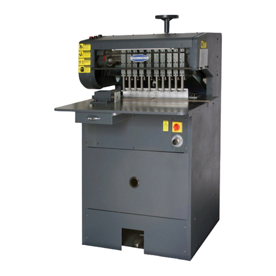
Page 14: Main Assemblies
5.0 Main Assemblies 5.1 Main Assembly – Front View A-6500-7 Rev. B... - Page 15 5.0 Main Assemblies Main Assembly – Front View – Parts List A-6500-7 Rev. B PART NO. DESCRIPTION 6501-1 SIDE FRAME - RIGHT HAND 6502-2 SIDE FRAME - LEFT HAND 6520-1 HANDWHEEL EE-3246 FOOTSWITCH ASSEMBLY H-6913-406 SCREW - 1/4-20 X 3/4 HEX HD H-7324-8 WASHER - 1/4 INT TOOTHLOCK H-6423-4...
- Page 16 Main Assembly – Front View – Parts List A-6500-7 Rev. B PART NO. DESCRIPTION H-6903-404 SCREW - 1/4-20 X 1/2" NYLOC BUT HD CAP P-325-F FELT - 2 X 2-1/8" EE-1489-3 LIGHT ASSEMBLY - TABLE/INTERLOCK SWITCH 4771-1 VALVE - BRONZE NEEDLE 6511 PULL DOWN BAR 6536...
-
Page 17: Main Assembly - Left Side Elevation
5.0 Main Assemblies 5.2 Main Assembly – Left Side Elevation A-6500-7 Rev. A... - Page 18 Main Assembly – Left Side Elevation – Parts List A-6500-7 Rev. A...
-
Page 19: Main Assembly - Rear Elevation
5.0 Main Assemblies 5.3 Main Assembly – Rear Elevation A-6500-7 Rev. D... - Page 20 Main Assembly – Rear Elevation – Parts List A-6500-7 Rev. D PART NO. DESCRIPTION OF ACCESSORIES 6504 DOVETAIL - VERTICLE S-1781-12 LABEL - SHOCK WARNING H-6918-608 SCREW - 3/8-16 X 1"SOC HD CAP 6593-1 SHAFT - SPINDLE MOTOR MOUNT 6584-2 PLATE - SPINDLE MOTOR S-1193-50 RETAINING RING - .500 DIA.
- Page 21 5.0 Main Assemblies Main Assembly – Rear Elevation – Parts List – (cont.) A-6500-7 Rev. D PART NO. DESCRIPTION OF ACCESSORIES H-6918-620 SCREW - 3/8-16 X 2-1/2" SOC HD CAP 6547 CHIP CHUTE - LOWER, RIGHT HAND 6550 CHIP CHUTE - LOWER, LEFT HAND E-1600-113 MOTOR- SPINDLE, 230V 3PH 50HZ E-1600-112...
-
Page 22: Main Assembly - Table
5.4 Main Assembly – Table A-6500-7 Rev. A... -
Page 23: Main Assembly - Large Diameter Drill Head Field Conversion
5.0 Main Assemblies 5.5 Main Assembly – Large Diameter Drill Head Field Conversion A-6500-7 Rev. B... - Page 24 Main Assembly – Large Diameter Drill Head Field Conversion – Parts List A-6500-7 Rev. B PART NO. DESCRIPTION OF ACCESSORIES A-6500-7 SHT BLUEPRINT OF ASSEMBLY H-5239-12 3/4-16 LT TH FLEX LOCK NUT 6670 LABEL 6672 PAPER GUIDE H-6910-606 3/8-16 X 3/4 BUTT HD SCR H-7324-12 3/8 SHAKEPROOF LOCKWASHER 6669...
- Page 25 See Power Lock-Out Procedure, page 5. The MS-10B Paper Drill can be easily altered to handle drilling of one or two holes up to 1-1/2” diameter, as well as handling standard drill work. Seven standard size hollow drills (listed below) are available for use with these large hole drilling heads.
- Page 26 Note: If chip chute extensions are ordered, install them before mounting the chip chute. See instructions for mounting instructions. D. (6) plastic drilling blocks 6669 E. Front table adapter 6667 Attach with paper guides 6672 or A-6565 if desired F. stops for drilling blocks 6590 G.
-
Page 27: Basic Machine Schematic
5.0 Main Assemblies 5.6 Basic Machine Schematic E-3231 Rev. A... -
Page 28: Interconnection Diagram
5.7 Interconnection Diagram E-3248 Rev. B... -
Page 29: Electrical Enclosure Assembly
5.0 Main Assemblies 5.8 Electrical Enclosure Assembly EE-3232 Rev. C... -
Page 30: Electrical Assembly - Control Panel
5.9 Electrical Assembly – Control Panel EE-3230 REV. “C”... - Page 31 5.0 Main Assemblies Electrical Assembly - Parts EE-3230 REV. “C” PART NO. DESCRIPTION OF ACCESSORIES PANEL – ELECTRICAL E-1084-4 E-1089-40 TRANSFORMER - 208/230/460 75VA E-2441-13 RELAY - OVERLOAD (H1), 7.5A to 11A (SPINDLE) E-2441-14 RELAY - OVERLOAD (H2), 4.5A to 6.5A (PUMP) E-2445-1 BRACKET - OVERLOAD RELAY E-2805...
-
Page 32: Hydraulic Power Unit Assembly
5.10 Hydraulic Power Unit Assembly H-566 Rev. B... -
Page 33: Standard Side Guide Assembly
5.0 Main Assemblies 5.11 Standard Side Guide Assembly A-6565 Rev. B... -
Page 34: Auto-Trip Side Guide Assembly
5.12 Auto-Trip Side Guide Assembly A-6565-3 Rev. F The auto-trip side guide, available as optional equipment, is mounted to the table in the same manner as the standard side guide. As the drill heads reach the bottom of their stroke, the trip lever is engaged, releasing the side guide and allowing the operator to slide the side guide to the left, to the next pre-determined stop. - Page 35 5.0 Main Assemblies Auto-Trip Side Guide Assembly A-6565-3 Rev. F...
- Page 36 F.399-DT August 2015...
Need help?
Do you have a question about the MS-10B and is the answer not in the manual?
Questions and answers