Table of Contents
Advertisement
Quick Links
The Challenge Machinery Company provides owner's manuals on its
products solely as a courtesy to its customers. See the information below
before using this manual.
These manuals are for reference only. These manuals include products which are noncurrent,
unsupported or no longer produced by The Challenge Machinery Company, and are provided solely as
an accommodation to our customers. By providing these manuals, The Challenge Machinery Company
makes no representation or warranty as to the products, their current condition, or their suitability or fitness
for use in any particular application, which are the sole and independent responsibility of the product
owner and user.
Older products may not comply with current safety procedures, guidelines or regulations, and it
is the product owner's and user's responsibility to evaluate the suitability and fitness of the
products in their current use and application. The Challenge Machinery Company makes no
representation, warranty or recommendation regarding any modifications which may be required
on non-current or unsupported products. The Challenge Machinery Company assumes no liability
for any modification or alteration to any Challenge product, and any such modification or
alteration to any Challenge product is not authorized by The Challenge Machinery Company. The
availability of these manuals is solely for the purpose of providing reference information for the products.
This manual may not be complete in all aspects of product maintenance and repair. All products should
be used only by qualified and properly trained personnel, following proper safety procedures. All
products should be regularly inspected and maintained, and their condition, application and use should
be periodically evaluated by qualified personnel. Only qualified and properly trained technicians should
perform maintenance, repair and replacement procedures. Attempting these procedures without proper
training may cause machine damage or operator injury!
Products may be unsupported by The Challenge Machinery Company due to age or the unavailability of
parts from their original manufacturer. No parts or product support will be available to repair or maintain
unsupported products. Older products may not be UL listed (if the product does not have a UL label it is
not a listed product), and may not comply with applicable installation or other regulations or requirements
if relocated to a new facility. Many municipalities require a product to be UL listed before an electrician
will connect power to them. Often the cost of updating an older product to comply with current safety
regulations is greater than the value of the product.
HANDY-DRILL
Instruction and Parts Manual
Serial Numbers:
055188 through 159999,
HDDR-A-150000 and up
Sold and Serviced by
The Challenge Machinery Company
6125 Norton Center Drive
Norton Shores, MI 49441-6081 USA
F.101-A
ChallengeMachinery.com
November 2015
Advertisement
Table of Contents

Related Manuals for Challenge Handy-Drill


Summary of Contents for Challenge Handy-Drill
- Page 1 Products may be unsupported by The Challenge Machinery Company due to age or the unavailability of parts from their original manufacturer. No parts or product support will be available to repair or maintain unsupported products.
-
Page 2: Introduction
DIRECTLY TO CHALLENGE. If you bought a used machine, it is important to have the following information on record at Challenge. Copy this page, fill in the information and send it care of The Challenge Service Department, 6125 Norton Center Drive, Norton Shores MI. -
Page 3: Table Of Contents
1.0 Introduction TABLE OF CONTENTS 1.0 Introduction ............................2 2.0 Safety ..............................4 2.1 Precautions ...........................4 2.2 Power Lockout Procedure ......................4 2.3 Warning Label Definitions ......................5 3.0 Packing List ............................7 4.0 Specifications ............................8 Minimum Distance Btw. Holes ......................8 5.0 Footprint ............................9 6.0 Installation & Setup ........................10 6.1 Inspecting Shipment ........................ -
Page 4: Safety
2.0 Safety 2.0 Safety 2.1 Precautions This machine is designed for one-person operation. Never operate the machine with more than one person. Always wear safety glasses while operating this machine. Safe use of this machine is the responsibility of the operator. Use good judgment and common sense when working with and around this machine. -
Page 5: Warning Label Definitions
2.0 Safety 2.3 Warning Label Definitions The following warning labels are found at various locations on your machine. Read and understand the meaning of each symbol. If a label is lost from the machine, it should be replaced. HAZARDOUS AREA Disconnect power before cleaning, servicing, or making adjustments not requiring power. - Page 6 2.0 Safety !OJO! This Este simbolo de alerta de seguridad significa ¡ OJO ! - INSTRUCCIONES DE SEGURIDADPERSONAL. Lea las instrucciones porque se refieren a su seguridad personal. Fall de obedecer las instrucciones que siguen podria resultar en lesiones corporales. ...
-
Page 7: Packing List
W-130 3/16 Hex Wrench W-192 3/32 Hex Wrench- Short Optional Items Part No. Description Qty. A-4682 Wood Drill Blocks (12 per container) 57100 Handy-Sharp Drill Bit Sharpener A-4950-1 Handy Chip Remover Replacement Bits See your Dealer for Original Challenge Bits... -
Page 8: Specifications
46 x 48cm Height Overall 22-3/8” 56.8cm Electrical 115 Volts, 2.7 Amps, 60Hz, 1 phase, AC. Use 3 Amp Slo-Blo fuse. Challenge reserves the right to make changes to any product or specification without notice and without incurring responsibility to existing units. -
Page 9: Footprint
5.0 Footprint 5.0 Footprint... -
Page 10: Installation & Setup
6.2 Uncrating The Handy-Drill weighs approximately 70 lbs (32 kg). DO NOT risk personal injury or damage by attempting to move machinery with makeshift equipment or inadequate help. This machine is shipped enclosed in a corrugated carton. Open the top of the carton and carefully lift machine out and set on to work surface. -
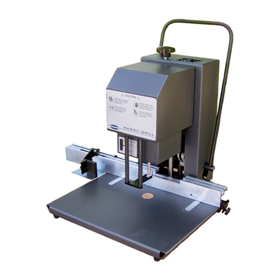
Page 11: Operation
Figure – Machine Controls 7.1 Set Hole Spacing The Handy-Drill backgauge has been set to drill standard three-ring holes, plus one extra stop for four-hole drilling. The stops are held in place with setscrews that run through the top of the stop. Use the 3/32”... -
Page 12: Drilling
7.0 Operation 7.3 Drilling After the machine has been properly installed and adjusted, it is ready for drilling. Set the side stop to the first position and jog stock against the backgauge and side guide. Switch on the machine by pressing the rocker switch to “I”. -
Page 13: Drilling Tips
Challenge. The Challenge Machinery Company assumes no liability for any modification or alteration to any Challenge products, and The Challenge Machinery Company does not authorize any such modification or alteration to any Challenge products. Any... - Page 14 8.0 Drilling Tips NOTES...
-
Page 15: Maintenance Section
Challenge. The Challenge Machinery Company assumes no liability for any modification or alteration to any Challenge products, and any such modification or alteration to any Challenge product is not authorized by The Challenge Machinery Company. Any modification or alteration of any Challenge product... -
Page 16: Routine Maintenance
9.0 Routine Maintenance 9.0 Routine Maintenance DISCONNECT POWER before making any adjustments or lubricating. See page 4, SAFETY PRECAUTIONS, for Power Lockout Procedure. A clean, lubricated machine will run longer and smoother, with less downtime and fewer repairs. Schedule lubrication both early in the day and early in the week. This allows the lubricants to work into the machine. -
Page 17: Troubleshooting
10.0 Troubleshooting 10.0 Troubleshooting Problem Possible Cause Solution The machine will not power a) Power cord is disconnected. a) Plug in cord. b) Blown fuse or circuit breaker b) Replace fuse c) Disconnected wires inside c) Check for wires that are machine. -
Page 18: Parts Lists
11.0 Parts Lists 11.0 Parts Lists 11.1 Main Assembly – Arch 64000 Sht. 1... - Page 19 11.0 Parts Lists Main Assembly – Arch 64000 Sht. 1 Item Part No. Description Qty. 6385 EXTENSION SPRING 64001 DRILL BASE 64005 GUIDE ROD 64007 MOTOR BRACKET 64008 FLANGE BEARING 64009 LEVER SHAFT 64010 PULL-DOWN LINK 64011 ADJUSTMENT ROD 64012 STOP 64013-1 PULL-DOWN LEVER...
-
Page 20: Main Assembly - Head
11.0 Parts Lists 11.2 Main Assembly – Head 64000 Sht. 2... - Page 21 11.0 Parts Lists Main Assembly – Head 64000 Sht. 2 Item Part No. Description Qty. 64007 MOTOR BRACKET A-10172-48 BEARING - SLEEVE A-10172-55 BEARING - SLEEVE...
-
Page 22: Main Assembly - Head
11.0 Parts Lists 11.3 Main Assembly – Head 64000 Sht. 3... - Page 23 11.0 Parts Lists Main Assembly – Head 64000 Sht. 3 Item Part No. Description Qty. 64006 SPINDLE FOR 2-1/2" HOLLOW DRILLS 64007 MOTOR BRACKET 64017 PRESSURE FOOT ASSEMBLY 64018 PRESSURE FOOT SPRING 64019 CHIP COLLECTOR MOUNT 64045 SWITCH ASSEMBLY 64046 SWITCH COVER 64050 MODIFIED MOTOR- 1/10 HP...
-
Page 24: Main Assembly - Covers
11.0 Parts Lists 11.4 Main Assembly – Covers 64000 Sht. 4... - Page 25 SCREW - #10-24 X 3/8 BUTTON HEAD CAP H-6918-102404 SCREW - #10-24 X 1/2 SOCKET HEAD CAP H-7321-#10 WASHER - #10 SAE PLAIN H-7324-#10 WASHER - #10 INT TOOTH S-1753-2 KNOB S-1781-143 LABEL- CHIP COLLECTOR S-1781-144 HANDY-DRILL NAMEPLATE S-1781-147 SCALE S-1781-152 "UP LABEL"...
-
Page 26: Backgauge Assembly
11.0 Parts Lists 11.5 Backgauge Assembly 64026... - Page 27 11.0 Parts Lists Backgauge Assembly 64026 Item Part No. Description Qty. 14001 PLATE- BACKGAUGE 64027 CLAMP BRACKET 64028 DOVETAIL PLATE 64029 PLATE- TABLE EXTENSION 64032 SIDE STOP ASSEMBLY 64033 SIDE STOP BLOCK 64048 BACKGAUGE- MACHINED 14036-1 STOP- BACKGAUGE 4599-3 STRIP PLATE- BACKGAUGE 8260-1 KNURLED KNOB A-7545...
-
Page 28: Interconnection Diagram
11.0 Parts Lists 11.6 Interconnection Diagram E-3161 REV. “D”... - Page 29 11.0 Parts Lists NOTES...
- Page 30 F.101-A November 2015...
Need help?
Do you have a question about the Handy-Drill and is the answer not in the manual?
Questions and answers