Table of Contents
Advertisement
SUBJECT: PES 5000 Version 3
SUBMITTED BY:
N. Tender/C. Harris/M. Furtaw
CHANGE TO BE IMPLEMENTED BY:
DOCUMENTATION AFFECTED: none
CATEGORY:
HARDWARE
EFFECTIVE DATE:
x
IMPLEMENT:
p
p
COMMENTS:
REMOVED MATERIAL DISPOSITION
SHIP TO
ATTENTION
COMMENTS
HUGHES NETWORK SYSTEMS
* * * PES CUSTOMER SERVICE BULLETIN * * *
AUTHORIZED HUGHES REPRESENTATIVE
x
FIRMWARE
5/11/2000
IMMEDIATELY
NEXT SERVICE CALL
OTHER
N/A
N/A
N/A
CSB NUMBER:
CSB ISSUE DATE:
APPROVED BY:
p
p
SOFTWARE
1
229
05/11/2000
Bayne Just
x
CUSTOMER
p
OTHER
CSB 229
p
Advertisement
Table of Contents

Related Manuals for Hughes PES 5000


Summary of Contents for Hughes PES 5000
- Page 1 CSB 229 HUGHES NETWORK SYSTEMS * * * PES CUSTOMER SERVICE BULLETIN * * * SUBJECT: PES 5000 Version 3 CSB NUMBER: CSB ISSUE DATE: 05/11/2000 SUBMITTED BY: N. Tender/C. Harris/M. Furtaw APPROVED BY: Bayne Just CHANGE TO BE IMPLEMENTED BY:...
-
Page 2: Table Of Contents
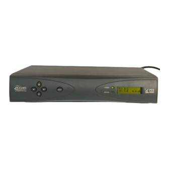
BACKGROUND HNS has introduced a new PES indoor unit, the PES 5000 version 3, as pictured in figure 1. The PES 5000 version 3 is functionally similar to prior PES 5000 products (with the minor restrictions that certain PLCs are not applicable to PES 5000 version 3, and certain software must be installed at the hub). -
Page 3: Material Required
Ku-band saturated ODU As shown in figure 2 the PES 5000 version 3 indoor unit has an “F” Type IFL connector. In earlier versions this was an “N” Type connector. There is presently a transition plan in place to migrate from “N” Type connectors on the IDU’s, ODU’s and IFL Cables to “F”... -
Page 4: "F" To "N"Adapters
“F” to “N”Adapters The “N” to “F” transition involves adapting the PES 5000 version 3 “F” Type connector on the back panel of the unit to the existing “N” Type IFL cable connector kits for Type I and Type III cable. The PES 5000 version 3 includes the proper adapters to convert its IFL “F”... -
Page 5: Action Required
IFL cable installation As shown in figure 2, the PES 5000 version 3 indoor unit has an F-type connector for the IFL cable. The present PES 5000 Outdoor Units have an N-type connector. Use the adapter(s) included in the indoor unit packaging box to connect the indoor unit to the IFL cable. - Page 6 CSB 229 top or it might abruptly slide toward the front and yank the ribbon cable, which connects the motherboard to the front panel circuit board. D) Tilt the cover/front panel assembly so the rear lifts away from the mother board/power supply chassis. At this point, you may choose to prop the cover/front panel assembly up to provide access.
- Page 7 CSB 229 99W0432.FH8 Figure 6. Slide Cover/Front Panel Assembly Forward and Tilt Up...
- Page 8 CABLE to FRONT PANEL Figure 7. Data Port PLC Orientation in PES 5000 Version 3 STEP 5. Replace the PES 5000 version 3 chassis cover/front panel assembly. Apply power to the PES 5000 version 3 and verify operation of the PLC.
-
Page 9: Pes 5000 Version 3 & Hub Software
PES 5000 version 3 indoor unit at a remote site. Note: At the time of this writing there may be release 8.0 Hub software in the field that will not operate PES 5000 version 3 remotes. Eventually, all release 8.0 software will support the PES 5000 version 3 remotes. The cluster-release number for Hub software that will operate with PES 5000 version 3 is 800.0030 or greater within the 8.0.NNN.NNNN series. -
Page 10: Rom Version Identification
0001 portion of the part number is not marked on the chip. Table 4 lists the REM MEM codes for the PES 5000 version 3 ROM chip. As described in CSB 226, the Hub operator may use the System Operator Console (SOC or VOC) and the listed REM MEM codes to determine the rev level of a ROM at a distant site. - Page 11 CSB 229 HUGHES OKEMO MOTHER BOARD FINGER THUMB POSITION POSITION AREA AREA SLOT FOR PLCC EXTRACTION TONG SLOT FOR EXTRACTION TONG EXTRACTION CORNER TONGS BEVELED EDGE 99w0428.fh8 Figure 9. Mother Board ROM Location and Identification...
-
Page 12: Using Diagnose Mode
To run diagnose mode, first remove power from the PES indoor unit and DISCONNECT THE IFL CABLE FROM THE REAR OF THE PES 5000 VERSION 3. Note that the IFL cable has to be disconnected in order to run the diagnostic IFL loopback test successfully. -
Page 13: Installation: Enter Card Type As 41
Installation: Enter Card Type as 41 NOTE: Until further notice, enter the card type as 41 for PES 5000 version 3. When the DIU Configuration Editor asks for the card type for SLOT 1, enter the card type to be 41. -
Page 14: Installation Includes Inroute 32 To F7Ff
Therefore, during installation always enter inroute 32 as F7FF. Figure 10 summarizes the installation process for PES 5000 version 3. The PC display 5/J. lasts for approximately 3 to 4 seconds and signifies that Hub has disaster recovery software and that inroute 32 has been properly entered as F7FF. -
Page 15: Placing Pes 5000 Version 3 In Auto Com Mode
Placing PES 5000 version 3 in AUTO COM mode The PES 5000 version 3 does not have an AUTO COM push-button as prior PES 5000 products do. To place the unit in AUTO COM mode, simultaneously press the left-arrow, up-arrow, and SELECT keys. The effect of AUTO-COM mode depends on whether the network for this remote is set for disaster recovery or not. -
Page 16: Multicolor Status Led
Whenever the indoor unit power is first applied, the PES 5000 version 3 Indoor Unit (IDU) conducts a series of self-tests, followed by re-establishment of communications with the hub. During this time, the multicolor STATUS LED indicates... - Page 17 CSB 229...
Need help?
Do you have a question about the PES 5000 and is the answer not in the manual?
Questions and answers