Table of Contents
Advertisement
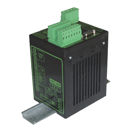
RESISTRON
RES-408
Operating
Instructions
Important features
•
Microprocessor technology
•
Separate terminal for operation and display
•
Automatic Zero Calibration (AUTOCAL)
•
Automatic optimization (AUTOTUNE)
•
Automatic Configuration of the secondary voltage and current ranges
(AUTORANGE, as of May 2006)
•
Automatic phase angle compensation (AUTOCOMP, as of June 2006)
•
Automatic frequency adjustment
•
Wide current and voltage range
•
0...10VDC analog output for ACTUAL temperature
•
24VDC control signals for START and PREHEAT with electrical isolation
•
Alarm function with fault diagnosis
•
Heatsealing Band alloy and temperature range selectable as standard (as of June 2006)
Industrie-Elektronik GmbH
Gansäcker 21
D-74321-Bietigheim-Bissingen (Germany)
GB
Tel: +49/(0)7142/7776-0
Fax: +49/(0)7142/7776-19
E-Mail:
info@ropex.de
Internet:
www.ropex.de
Data subject to change
Advertisement
Table of Contents

Related Manuals for Ropex RESISTRON RES-408


Summary of Contents for Ropex RESISTRON RES-408
- Page 1 24VDC control signals for START and PREHEAT with electrical isolation • Alarm function with fault diagnosis • Heatsealing band alloy and temperature range selectable as standard (as of June 2006) Industrie-Elektronik GmbH Tel: +49/(0)7142/7776-0 E-Mail: info@ropex.de Gansäcker 21 Fax: +49/(0)7142/7776-19 Internet: www.ropex.de D-74321-Bietigheim-Bissingen (Germany) Data subject to change...
- Page 2 Contents Safety and warning notes ....3 Controller functions ....24 Use .
- Page 3 The resistance of the heatsealing band which Only the original ROPEX PEX-W2 or PEX-W3 is used must have a positive minimum tem- current transformer may be used. Other perature coefficient in order to guarantee trouble-...
- Page 4 Line filter DIN EN 61010-1 Safety provisions for electrical The use of an original ROPEX line filter is mandatory in (VDE 0411-1) measuring, control and laboratory order to comply with the standards and provisions men- devices (low voltage directive).
- Page 5 Principle of operation The use of RESISTRON temperature controllers • Increased machine capacity results in: • Extended life of the heatsealing bands and teflon coatings • Repeatable quality of the heatseals under any con- ditions • Simple operation and control of the sealing process Principle of operation The resistance of the heatsealing band, which is tem- transformer.
- Page 6 Description of the controller Description of the controller The microprocessor technology endows the RES-408 The temperature can be set on the separate T-408-1 RESISTRON temperature controller with previously (or T-400) operator terminal. unattainable capabilities: The real heatsealing band temperature is also visua- lized on the operator terminal.
- Page 7 Designed according to VDE 0570/EN 61558 with a one-section bobbin. Optimized for impulse operation with RESISTRON temperature controllers. Specified according to the heatsealing application ROPEX Application Report). CI-USB-1 communication interface Interface for connecting a RESISTRON temperature controller with a diagnostic interface (DIAG) to the PC (USB port).
- Page 8 Accessories and modifications Modifications (MODs) MOD 01 Amplifier secondary voltages Owing to its universal design, the RES-408 RESIS- = 0.25…16VAC). This modification is necessary, TRON temperature controller is suitable for a very wide for example, for very short or low-resistance heat- range of heatsealing applications.
- Page 9 The temperature range and temperature coefficient settings can also be specified range in the ROPEX visualization software ( section 11.16 "Diagnostic interface / visualization software (as of June 2006)" on page 37) in addition to using the...
- Page 10 Technical data Alarm relay = 50VDC, I = 0.2A, changeover contact, potential-free Terminals 12, 13, 14 Can be inverted by means of a plug-in jumper Maximum load = 5A (duty cycle = 100%) (primary current of = 25A (duty cycle = 20%) impulse transformer) Power loss max.
- Page 11 Controller/terminal compatibility Controller/terminal compatibility All RES-408 RESISTRON temperature controllers This has no effect on temperature control or on the manufactured as of June 2006 are supplied as an external PLC control signals. upgraded version. RES-408 controllers manufactured as of Among other things, the data transfer between the con- June 2006 are fully electrically compatible troller and the terminal has been modified.
- Page 12 Dimensions Dimensions RES-408 controller 75.0 90.0 T-400 or T-408-1 terminal front panel panel cutout o 5mm +0.8 +0.6 x 45 55.0 56.0 outline dimensions front frame Page 12 RES-408...
- Page 13 9.3 "Power supply" on page 15 and the the RESISTRON temperature controller must be ROPEX Application Report. The information pro- identical to the line voltage that is present in the vided in section 9.2 "Installation steps" on page 14 plant or machine.
- Page 14 Installation Installation steps Use heatseal bands with suitable temperature coefficient Heatseal element push-on with coppered ends connectors Heatsealing band R= f (T) No additional Connect U measuring resistance wires directly to in secondary Note heatsealing band ends circuit number Sufficient wire of turns Twisted cross-section...
- Page 15 Installation Power supply LINE Line L1 (L1) 115VAC, 230VAC, 400VAC N (L2) GND/ Earth Circuit breaker Double-pole, C characteristic ROPEX Application Report) Short-circuit protection only. > > RESISTRON-Temperaturreglers not protected. Relay Ka "HEAT ON - OFF" function (all-pole) "EMERGENCY STOP".
- Page 16 CE mark. The wiring instructions contained in section 9.3 "Power ROPEX line filters are specially optimized for use in supply" on page 15 must be observed. RESISTRON control loops. Providing that they are Large cross-section wire to ground max.
- Page 17 Current transformer date PEX-W2/-W3 May 2006 °C (Internal ground) ANALOG No external OUTPUT grounding allowed! +0...10VDC ROPEX T-408 SEALHEAT PREHEAT HOLD ENTER HAND RESET Display- and operation panel Up to production date March 2003 the standard output power circuit (terminals 3+4) has NO function when the booster-connection (MOD 26) is installed.
- Page 18 Current transformer date PEX-W2/-W3 May 2006 °C (Internal ground) ANALOG No external OUTPUT grounding allowed! +0...10VDC ROPEX T-408 SEALHEAT PREHEAT HOLD ENTER HAND RESET Display- and operation panel Up to production date March 2003 the standard output power circuit (terminals 3+4) has NO function when the booster-connection (MOD 26) is installed.
- Page 19 Startup and operation Startup and operation 10.1 View of the controller RES-408 controller LEDs Terminals Connection for terminal Wiring diagram Nameplate Coding switches and plug-in jumpers T-400 or T-408-1 terminal Nameplate Cable connection Display Fixing clips (4x) Operator keys RES-408 Page 19...
- Page 20 (as of June 2006) You can find the exact configuration of the The secondary voltage and current ranges are automa- DIP switches in the ROPEX Application tically configured by the automatic calibration function Report calculated for your particular application. (AUTOCAL). The voltage is configured in the range from 0.4VAC to 120VAC and the current in the range...
- Page 21 GURATION" position is selected (as of June 2006), the The measuring principle applied for this system neces- behavior of the alarm output can be configured more sitates a heatsealing band alloy with a suitable tempe- finely in the ROPEX visualization software ( RES-408 Page 21...
- Page 22 May 2006, the DIP switches on the controller must in the alloying properties stabilized. be set according to the ROPEX Application Report The burn-in effect described here does not occur if the and depend on the heatsealing band that is used heatsealing band has already been thermally pret- (section 10.2 "Controller configuration"...
- Page 23 June 2006. In this case the controller configuration 7. One of the following states then appears: is incorrect ( section 10.2 "Controller configura- tion" on page 20 and ROPEX Application Report). Controllers manufactured as of June 2006: Repeat the calibration after the controller has been configured correctly.
- Page 24 Yellow LED, remains lit for duration of AUTOCAL process. RESISTRON RES- 408 Temperature controller ROPEX Tel:+49(0)7142-7776-0 Made in Germany In addition to the functions shown in the diagram controller LEDs. These states are described in detail in above, various operating states are indicated by the...
- Page 25 Controller functions T-408-1 terminal LED display, 5 characters ROPEX T-408 SEALHEAT 1 Green LED: Heatung up/temp. control PREHEAT to set temperature active HOLD 2 Yellow LED: PREHEAT active ENTER 3 Green LED: Hold mode active HAND RESET “UP” and “DOWN” keys for setting values Press (<...
- Page 26 Green LED, indicates pulses in measure- POWER ON ment mode. In control mode, luminous OUTPUT intensity is proportional to heating current. RESISTRON µP-Controller ROPEX INDUSTRIE - ELEKTRONIK T-400 terminal LED display, 5 characters ROPEX SEALHEAT PREHEAT 1 Red/Green LED: Red, during heating up Green, set temp.
- Page 27 37). On controllers manufactured as of June 2006, this message shows the SW revision of the terminal for the first 1.5s (e.g.: 00.105) and the SW revision of the con- ROPEX T-408 SEALHEAT troller for the next 1.5s (e.g.: 00.105).
- Page 28 Controller functions 11.4 Menu structure 1) AUTOCOMP: OFF Power-up message 2) AUTOCOMP: ON Home position °C SH Heatsealing temp. Preheat temp. Autocal? Autocal Autocomp? Autocomp Fault Alarm Autocal? Autocal Page 28 RES-408...
- Page 29 Controller functions 11.5 Menu steps Name Description Setting range °C Home position The current actual value appears on the terminal display. The heatsealing band can be heated manually (to the specified heatsealing or preheat temperature) by pressing the "HAND" key. [HAnd] The heatsealing band can be heated manually (to Hand menu...
- Page 30 Controller functions Name Description Setting range [AutoCal] The AUTOCAL function matches the controller to Controllers manufactured Automatic calibra- the current and voltage signals that are present in up to May 2006: tion AUTOCAL the system. Setting not possible The required calibration temperature can be set with the "UP"...
- Page 31 0…10VDC June 2006. 11.7 Temperature indication / actual 0…10VDC value output If the display is in the home position ("°C"), the Temperature ACTUAL temperature is indicated. meter e.g. ATR-3 ROPEX T-408 SEALHEAT PREHEAT HOLD ENTER HAND RESET RES-408 Page 31...
- Page 32 17+18) is set to 0…3°C (corresponds to approxi- sealing band. mately 0 VDC) until the function has ended. The characteristics of the ROPEX ATR-x temperature If the temperature of the heatsealing band varies on meter (size, scaling, dynamic response) are optimized...
- Page 33 Controller functions times. If the function still cannot be terminated suc- The "START" signal is activated by applying a 24VDC cessfully, an error message appears ( section 11.18 signal at terminals 5+6. "Error messages" on page 38). 24VDC RES-408 START You should always wait for the heatsealing (HEAT) band and the bar to cool down (to ambient...
- Page 34 Controller functions 11.10 "PREHEAT" signal "START" signal 24VDC The heatsealing band can be heated to a specified pre- heat temperature with the "PREHEAT" function, in order to shorten the heating time to the selected SET temperature in time-critical applications. "PREHEAT" The preheat temperature is set with the "PH"...
- Page 35 1.7ms for certain applications heatsealing phase. ROPEX Application Report). Hold mode only affects the value on the dis- This parameter can only be set in the ROPEX play. The ACTUAL temperature is always visualization software ( section 11.16 "Dia-...
- Page 36 ∆ϑ ) tolerance band limits are configured in the upper factory to -10K and +10K. These values can be set independently of one another in the ROPEX visualiza- tion software. Function AUTOCOMP If the ACTUAL temperature is inside the specified tole- rance band when the "START"...
- Page 37 ROPEX visualization software ( section 11.16 "Dia- gnostic interface / visualization software (as of The ROPEX visualization software is described in a June 2006)" on page 37). separate document. This timeout starts when the START signal is activated.
- Page 38 The error codes described Selective fault detection and indication can thus be below can be displayed in the ROPEX visualization implemented simply and inexpensively using the software ( section 11.16 "Diagnostic interface / visua-...
- Page 39 Controller functions RES-408 Page 39...
- Page 40 Controller functions Page 40 RES-408...
- Page 41 Controller functions RES-408 Page 41...
- Page 42 Controller functions Page 42 RES-408...
- Page 43 Controller functions 11.19 Fault areas and causes Temperaturregler HARDWARE The table below explains the possible fault causes. Fault area Explanation Possible causes Load circuit interrupted after U - Wire break, heatsealing band break - Contacting to heatsealing band defective pickoff point PEX-W2/-W3 current transformer measuring wires from current transformer interrupted signal interrupted...
- Page 44 Factory settings Fault area Explanation Possible causes - Up to May 2006: DIP switches 4 + 5 configured incorrectly range) signal incorrect - As of June 2006: I outside permissible range from 30…500A Turns through PEX-W2/-W3 cur- - Check number of turns (two or more turns required for rent transformer incorrect currents <...
- Page 45 Heatup Heatup timeout: OFF timeout [X] As of June 2006: Only in ROPEX visualization software Maintenance The controller requires no special maintenance. the impulse transformer – is recommended. Dust depo- Regular inspection and/or tightening of the terminals – sits on the controller can be removed with dry com- including the terminals for the winding connections on pressed air.
- Page 46 Line filter LF- . . 480 06: Continuous current 6A, 480VAC, Art. No. 885500 35: Continuous current 35A, 480VAC, Art. No. 885506 Impulse transformer See ROPEX Application Report for design and ordering information Communication interface CI-USB-1 Art. No. 885650 Page 46...
- Page 47 How to order Temperature meter ATR- . 3: 300°C range, Art. No. 882130 5: 500°C range, Art. No. 882150 Booster B- . . . 400 075: Max. pulse load 75A, 400VAC, Art. No. 885301 100: Max. pulse load 100A, 400VAC, Art. No. 885304 For more accessories: "Accessories"...
- Page 48 Index Index Accessories Impulse heatsealing method Actual value output Impulse transformer Alarm output Installation Alarm relay Installation procedure Alloy Installation regulations Ambient temperature Analog input Analog output Line filter Analog temperature meter Line frequency Application Line voltage Application Report AUTOCAL AUTOCOMP Maintenance Automatic phase compensation...
- Page 49 Index Temperature meter Temperature range View of the controller Temperature setting Visualization software Transformer Type of construction Wiring Wiring diagram RES-408 Page 49...
Need help?
Do you have a question about the RESISTRON RES-408 and is the answer not in the manual?
Questions and answers