
Subscribe to Our Youtube Channel
Related Manuals for Viega 8655.11


Summary of Contents for Viega 8655.11
- Page 1 Instructions for Use Electronics accessory set For electronic WC flush plates for Prevista Model Year built (from) 8655.11 03/2019...
-
Page 2: Table Of Contents
Table of contents Table of contents About these instructions for use 1.1 Target groups 1.2 Labelling of notes 1.3 About this translated version Product information 2.1 Standards and regulations 2.2 Safety advice 2.3 Intended use 2.3.1 Areas of use 2.4 General notes 2.5 Product description 2.5.1 Overview... -
Page 3: About These Instructions For Use
This restriction does not extend to possible operating instructions. The installation of Viega products must take place in accordance with the general rules of engineering and the Viega instructions for use. -
Page 4: About This Translated Version
About these instructions for use About this translated version This instruction for use contains important information about the choice of product or system, assembly and commissioning as well as intended use and, if required, maintenance measures. The information about the products, their properties and application technology are based on the current standards in Europe (e.g. -
Page 5: Product Information
Product information Product information Standards and regulations The following standards and regulations apply to Germany / Europe and are provided as a support feature. Regulations from section: Fields of application / Mounting conditions Scope / Notice Regulations applicable in Ger‐ many Protection area for installation of VDE 0100-701... -
Page 6: General Notes
Product information General notes If you notice any damage on the product or individual components, do not carry out a repair. Instead, have the product replaced by qualified personnel. This product is not intended for use by persons (including children) with restricted physical, sensory or mental aptitude or lack of experi‐... -
Page 7: Product Description
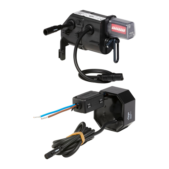
Product information Symbol Description The marked product must not be disposed of as household waste. Product description 2.5.1 Overview Electronic drive unit Power pack Terminal Electronics accessory set... -
Page 8: Technical Data
Product information 2.5.2 Technical data Electronics Input (power pack) 100–240 V AC, 50–60 Hz, 100 mA Output (power pack) 6.5 V DC, 800 mA Electrical approvals see section Ä „Regulations from sec‐ tion: Technical data“ on page 5. Voltage and current Motor Voltage [V] Current [mA]... -
Page 9: Accessories
Product information Accessories Optional accessories installation set (model 8640.14) The installation set contains a hollow wall socket to house the power pack and an empty pipe to connect the cistern. Extension cable (model 8352.690) 2 metre cable for the extension of the power supply. Use a maximum of two extension cables with the power pack (4.75 meter total length). -
Page 10: Handling
Handling Handling Assembly information 3.1.1 Mounting conditions Installation position of the power pack The power pack should be mounted in an easily accessible place to allow subsequent access. Before beginning to clad, a concealed socket should be installed for the power pack with empty pipe to the cistern (installation set Ä... -
Page 11: Required Material And Tools
0 and 1 of shower rooms and bathrooms is not per‐ mitted, see Ä „Regulations from section: Fields of application / Mounting conditions“ on page 5. Viega recommends installing the power pack outside of the protected zones 0–2. 3.1.2 Required material and tools... - Page 12 The assignment of the DIP switches: Switches 1-4 define the flush volume. Switches 5-7 define the interval of the Viega Hygiene+ function. Switch 8 defines the flush volume of the Viega Hygiene+ function. NOTICE! Damage due to moisture Risk of damage to the drive unit if moisture penetrates.
- Page 13 Program 6 Program 7 Program 8 Program 9 Program 10 Viega Enabling the Hygiene+ function and setting the intervals (B) Interval (in hours) Position of switches 5—7 Switched off Setting the flush volume of the Viega Hygiene+ function (C) Flush volume (in litres)
-
Page 14: Mounting With Flush Plate In Front Position
Handling 3.2.2 Mounting with flush plate in front position DANGER! Danger due to electrical current An electric shock can lead to burns and serious injury and even death. Only allow electrical work to be carried out by qualified electricians. Always de-energise the connection cable before work is commenced. - Page 15 Handling Requirements: A 230 V mains connection is available on site. The installation position of the power pack complies with the require‐ ments in acc. with Ä Chapter 3.1.1 „Mounting conditions“ on page 10. The connection cable is de-energised. ▶ Remove the shaft cover.
- Page 16 Handling ▶ Put the power pack in place. ▶ Remove approx. 1 cm of the insulation on the cables. ▶ Push the cables into the terminals. INFO! Use the cable feedthrough. ▶ Route the connection cable from the power pack through the empty pipe into the cistern.
- Page 17 Handling ▶ Let the drive unit engage in the mechanism. ▶ Turn the cover plate 180°. ▶ Connect the clip of the mechanism and the drive unit to the eye. ▶ Apply the silicon grease to all drive unit connections. Electronics accessory set...
- Page 18 Handling ▶ To establish the power supply, connect the short cable of the drive unit to the power pack. ▶ Guide the long cable of the drive unit forward through the cover plate. ▶ Insert the cover plate into the cistern. ▶...
-
Page 19: Mounting With Flush Plate In Top Position
Handling 3.2.3 Mounting with flush plate in top position DANGER! Danger due to electrical current An electric shock can lead to burns and serious injury and even death. Only allow electrical work to be carried out by qualified electricians. Always de-energise the connection cable before work is commenced. - Page 20 Handling Requirements: A 230 V mains connection is available on site. The installation position of the power pack complies with the require‐ ments in acc. with Ä Chapter 3.1.1 „Mounting conditions“ on page 10. The connection cable is de-energised. ▶ Remove the shaft cover.
- Page 21 Handling ▶ Remove the site protection. ▶ Put the power pack in place. ▶ Remove approx. 1 cm of the insulation on the cables. ▶ Push the cables into the terminals. INFO! Use the cable feedthrough. ▶ Route the connection cable from the power pack through the empty pipe into the cistern.
- Page 22 Handling ▶ Place the drive unit on the mechanism. ▶ Let the drive unit engage in the mechanism. ▶ Connect the clip of the mechanism and the drive unit to the eye. ▶ Apply the silicon grease to all drive unit connections. Electronics accessory set...
- Page 23 Handling ▶ To establish the power supply, connect the short cable of the drive unit to the flushing station. ▶ Place the mechanism with the drive unit into the rear of the cover plate. ▶ Hang the mechanism in the tab of the drain valve. ▶...
-
Page 24: Disposal
Handling ▶ Insert the cover plate into the cistern. ▶ Turn the cover plate lock by 90° in a clockwise direction. ▶ Insert the shaft cover. ▷ The drive unit has been mounted. Disposal Separate the product and packaging materials (e. g. paper, metal, plastic or non-ferrous metals) and dispose of in accordance with valid national legal requirements. - Page 25 Viega Technology GmbH & Co. KG service-technik@viega.de viega.com INT • 2020-07 • VPN190609...
Need help?
Do you have a question about the 8655.11 and is the answer not in the manual?
Questions and answers