Advertisement
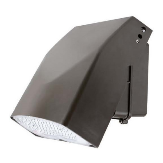
WTA Series
Installation Instructions
READ AND FOLLOW ALL SAFETY INSTRUCTIONS.
When using electrical equipment, basic safety precautions should always be followed including the following:
• DISCONNECT AC POWER SUPPLY BEFORE SERVICING.
• Installation and servicing of this equipment should be performed by qualified service personnel only.
• Ensure that the electrical wiring conforms to the National Electrical Code NEC® and local regulations
if applicable.
• Do not mount near gas or electrical heaters.
• Equipment should be mounted in locations and at heights where it will not be readily subjected to tampering
by unauthorized personnel.
• The use of accessory equipment not recommended by the manufacturer may cause an unsafe condition.
• Any modification or use of non-original components will void the warranty and product liability.
• Do not use this equipment for other than intended use.
20070162 REV 1 - 04/20
IMPORTANT SAFEGUARDS
SAVE THESE INSTRUCTIONS!
Technical Support
■ (623) 580-8943 ■ technicalsupport@barronltg.com
1
800-533-3948 www.barronltg.com
Advertisement
Table of Contents

Related Manuals for BARRON TRACE-LITE WTA Series


Summary of Contents for BARRON TRACE-LITE WTA Series
- Page 1 WTA Series Installation Instructions IMPORTANT SAFEGUARDS READ AND FOLLOW ALL SAFETY INSTRUCTIONS. When using electrical equipment, basic safety precautions should always be followed including the following: • DISCONNECT AC POWER SUPPLY BEFORE SERVICING. • Installation and servicing of this equipment should be performed by qualified service personnel only. •...
- Page 2 WTA Series Installation Instructions MOUNTING TO A WALL 1. Open the Back Box by loosening the Locking Screw. 2. Verify and remove only necessary EVA Gasket material where Back Box will mount. 3. Knock-out Back Box material for necessary mounting location. 4.
- Page 3 WTA Series Installation Instructions ANGLE ADJUSTMENT If the light output angle needs to be adjusted, loosen screw to rotate the fixture to desired light output angle. Tighten screw once desired light output angle is achieved. 60° 90° 0° Serrated Safety Screw Washers Adjusting angle screw...
- Page 4 WTA Series Installation Instructions Wiring Standard Black Line Electrical connections should be made inside J-box. Cap all unused leads to prevent shorting. Neutral White Green/Yellow Green Ground Make electrical connections as follows: Purple DIM+ Black - Line Gray DIM- White - Neutral Green/Yellow Green - Ground Photocontrol Note: This fixture auto adjusts for voltages from...
Need help?
Do you have a question about the TRACE-LITE WTA Series and is the answer not in the manual?
Questions and answers