Table of Contents
Advertisement
Advertisement
Table of Contents

Related Manuals for Chattanooga 3D ActiveTrac


Summary of Contents for Chattanooga 3D ActiveTrac
- Page 1 Moving ® Rehabilitation Forward™ User Manual 120V Treatment Tables...
-
Page 2: Table Of Contents
ABOuT 3d ACTivETrAC . . . . . . . . . . . . . . . . . . . -
Page 3: Foreword
The 3D ActiveTrac consists of an adjustable treatment table equipped with a traction force generator. It is designed to exert a therapeutic distraction force on the patient’s spine to relieve pressures on structures that may be causing pain. It produces the forces and positions required to cause decompression of the intervertebral discs, that is, unloading due to distraction and positioning. -
Page 4: About 3D Activetrac
ABOuT 3d ACTivETrAC ® 3D ActiveTrac prECAuTiONAry iNSTruCTiONS The precautionary instructions found in this section and throughout this manual are indicated by specific symbols. Understand these symbols and their definitions before operating this equipment. The definitions of these symbols are as follows: EXPLOSION HAZARD- Text with an “Explosion Hazard”... - Page 5 ABOuT 3d ACTivETrAC ® 3D ActiveTrac • This table should be operated in temperatures between • Read, understand, and practice the precautionary and 59° F (15° C) and 95° F (35° C), with relative humidity operating instructions found in this manual. Know the ranging from 20% - 75%.
- Page 6 • Never transport a patient on the 3D ActiveTrac. This table is • Possible explosion hazard if used in the presence of not designed to support a patient during transport.
-
Page 7: Indications For Use
ABOuT 3d ACTivETrAC ® 3D ActiveTrac iNdiCATiONS FOr uSE rELATivE CONTrAiNdiCATiONS (rEquirES SpECiAL mONiTOriNg Or Conditions that may be treated include back pain, neck pain, ShOuLd BE AvOidEd) herniated disc, protruding disc, degenerative disc disease, posterior facet syndrome and sciatica. -
Page 8: Nomenclature
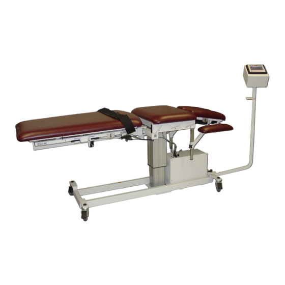
NOmENCLATurE ® 3D ActiveTrac TABLE FAmiLiArizATiON TOUChSCREEN CONTROL pANEL (TCp) ANChOR pOINTS fOR SLImLINE SLImLINE bELTS STAbILIzATION bELT ROTATION LEVER ADJUSTAbLE pOWER ARmRESTS ON/Off SWITCh LOCk/UNLOCk SIDE bENDING hANDLE LEVER pOWER CONTROL LOCkING CASTERS (ON ALL fOUR WhEELS) -
Page 9: Explanation Of Features
NOmENCLATurE ® 3D ActiveTrac ExpLANATiON OF FEATurES Touchscreen Control Panel (TCP) Power Control Box The Touchscreen Control Panel (TCP) is a touchscreen user The Power Control Box is at the cervical end of the table. The interface for entry of traction parameters. The TCP attachment Power On-Off Switch, power cord and power receptacle are rotates in a 180°... - Page 10 NOmENCLATurE ® 3D ActiveTrac ExpLANATiON OF FEATurES (CONTiNuEd) Table Adjustment Control Table Lock-Unlock A. High/Low Adjustment The lumbar section of the table must be locked in the closed position during patient set-up. It must be unlocked for lumbar You can vary the height of the table from 23 to 35 inches using traction.
- Page 11 NOmENCLATurE ® 3D ActiveTrac ExpLANATiON OF FEATurES (CONTiNuEd) Table Rotation Lever Pelvic and Thoracic Harnesses Table rotation (15 degrees from neutral) is controlled with The Pelvic and Thoracic Harnesses should be used for most squeeze and release of levers located on either side of the lumbar traction treatments.
- Page 12 NOmENCLATurE ® 3D ActiveTrac ExpLANATiON OF FEATurES (CONTiNuEd) Slimline Stabilization Belts Cervical Traction Accessory The Slimline Stabilization Belts can be used for pelvic traction, To install the Cervical Traction Accessory: mobilization, manipulation or exercise. The Lumbar Stabilization a. Slide the Cervical Traction Accessory into the face slot from Belt should be fitted with a sacral pad (provided) for additional the top.
- Page 13 ExpLANATiON OF FEATurES (CONTiNuEd) Lumbar Traction Excursion Limitations Cervical Traction Excursion Limitations The lumbar section of the 3D ActiveTrac has 6 inches maximum The 3D ActiveTrac’s cervical traction mechanism has 4 inches excursion. If the table reaches maximum excursion during maximum excursion.
-
Page 14: Specifications
SpECiFiCATiONS ® 3D ActiveTrac TABLE SpECiFiCATiONS Parameter 120V* Electrical Rating: 120VAC, 60 Hz, 5 Amp (USA) Fuse Rating: 125V, T5AL (USA) Lifting Capacity: 300 lbs (136 kg) Electrical Safety Classification: Class I Electrical Type: Type B IN ACCORDANCE WITh EN 60601-1, EN 60601-2 mEDICAL ELECTRICAL EQUIpmENT CERTIfIED * MODEL NUMBERS: Model 8025 –... -
Page 15: Installation
® 3D ActiveTrac 1. Remove packaging materials. ON/OFF SWITCH 2. Attach the Touchscreen Control Panel (TCP) to the 15 PIN cervical end of the table CONNECTOR using the four, 1/4” x 1” buttonhead, socket head cap screws using a 5/32 hex-key POWER (Figure 1). -
Page 16: Operation
OpErATiON ® 3D ActiveTrac uSiNg ThE pELviC ANd ThOrACiC hArNESSES 1. The Thoracic Harness features two rectangular rings for 2. Adjust the length of the Thoracic Harness straps as needed attachment of the straps. Use the outermost rings for large by securing the hook and loop in the desired position. - Page 17 OpErATiON ® 3D ActiveTrac uSiNg ThE pELviC ANd ThOrACiC hArNESSES (CONTiNuEd) 5. Adjust the position of the Pelvic Harness so that it slightly 8. Adjust the position of the table as needed (lumbar section overlaps on top of the Thoracic Harness as shown.
- Page 18 OpErATiON ® 3D ActiveTrac uSiNg ThE pELviC ANd ThOrACiC hArNESSES (CONTiNuEd) 13. Use pillows, bolsters or the flexion stool as desired for 12. After securing the harnesses, pull all the slack out of the positioning. harness straps by first pulling on the Pelvic Harness straps at the lumbar end of the table until both harnesses are taut.
-
Page 19: Using The Slimline Stabilization Belt System
OpErATiON ® 3D ActiveTrac uSiNg ThE SLimLiNE STABiLizATiON BELT SySTEm 1. Thread the Slimline belts through the desired belt loops. 4. Make sure the table is locked in the closed position before There are three optional positions for the Thoracic getting the patient on the table. - Page 20 OpErATiON ® 3D ActiveTrac uSiNg ThE SLimLiNE STABiLizATiON BELT SySTEm (CONTiNuEd) 8. Prone Position: Secure the Pelvic Stabilization Belt so that the top of the belt is at the lumbosacral junction and the sacral pad is in full contact with the sacrum. Choose the...
-
Page 21: Lumbar Traction Treatment Procedure
OpErATiON ® 3D ActiveTrac LumBAr TrACTiON TrEATmENT prOCEdurE 1. Once patient is positioned and secured, turn the lock/unlock 6. When the treatment is over, traction gently releases by itself. handle to unlock the lumbar section of the table. Turn the lock/unlock handle to lock the lumbar section of the table. - Page 22 OpErATiON ® 3D ActiveTrac LumBAr TrACTiON TrEATmENT prOCEdurE (CONTiNuEd) • Monitor excursion identification markings to assure full excursion has not been reached. • If patient repositioning is required, you should Stop rather than Pause the unit, so that you can close and lock the table during repositioning. You cannot close the table during Pause mode. • If you repositioned the patient, remember to take up the slack in the harness straps by pulling on the Pelvic Harness straps at the lumbar end of the table.
-
Page 23: Cervical Traction Treatment Procedure
OpErATiON ® 3D ActiveTrac CErviCAL TrACTiON TrEATmENT prOCEdurE 1. Make sure the table is locked in the closed position before getting the patient on the table (turn the lock/unlock handle). The table should remain locked in the closed position for cervical traction treatment. - Page 24 OpErATiON ® 3D ActiveTrac CErviCAL TrACTiON TrEATmENT prOCEdurE (CONTiNuEd) 6. Use pillows, bolsters or the optional flexion stool as desired for position of the lower extremities. 7. Give the patient the Patient Control Switch and instruct in its use. 8. Use the Touchscreen Control Panel (TCP) to enter the desired treatment protocol.
- Page 25 TOuChSCrEEN CONTrOL pANEL (TCp) This section defines the operation of the Touchscreen Control Next Panel for the 3D ActiveTrac. Each one of the screens is Pressing Next advances to the next screen. Press Next when illustrated and explained below. you have finished selecting either Cervical or Lumbar mode.
- Page 26 OpErATiON ® 3D ActiveTrac TOuChSCrEEN CONTrOL pANEL (TCp) (CONTiNuEd) Static/Intermittent Next Pressing this icon will toggle between the Static and the Pressing Next advances to the next screen. Press Next when Intermittent modes of operation. The Static mode ramps up you have finished selecting Static or Intermittent mode;...
-
Page 27: Touchscreen Control Panel (Tcp)
OpErATiON ® 3D ActiveTrac TOuChSCrEEN CONTrOL pANEL (TCp) (CONTiNuEd) Heading Ramp Down Time The heading on this screen will correspond to the treatment The ramp down time is the amount of time that it takes to mode you previously selected (Cervical or Lumbar; Static or completely release the force at the end of treatment. - Page 28 OpErATiON ® 3D ActiveTrac TOuChSCrEEN CONTrOL pANEL (TCp) (CONTiNuEd) Hold Time and Rest Time The initial Hold time will begin when the maximum force has been achieved (at the end of the Ramp up time). During the Hold time, the maximum force you set will be held. During the Rest time, the lesser force you set will be held.
- Page 29 OpErATiON ® 3D ActiveTrac TOuChSCrEEN CONTrOL pANEL (TCp) (CONTiNuEd) The Rest Force Screen allows you to set the force that will apply Next during the Rest phase of treatment in Intermittent mode. The Pressing Next advances to the next screen. Press Next when Rest force is set as a percentage of the Hold force.
- Page 30 OpErATiON ® 3D ActiveTrac TOuChSCrEEN CONTrOL pANEL (TCp) (CONTiNuEd) Back Treatment Time Set Pressing Back returns to the previous screen. Press Back if you The Treatment Time Set option allows you to enter the number wish to change a selection on a previous screen.
- Page 31 OpErATiON ® 3D ActiveTrac TOuChSCrEEN CONTrOL pANEL (TCp) (CONTiNuEd) To set the treatment time, press the box under “Treatment Force Set Time”. A numeric display will appear. Enter a 2 digit number The Force Set option allows you to enter the maximum by pressing the keys (the number you entered appears in the treatment force.
- Page 32 OpErATiON ® 3D ActiveTrac TOuChSCrEEN CONTrOL pANEL (TCp) (CONTiNuEd) On the Treatment Display screen, all parameters are updated according to real-time conditions. You can change Time and Force without starting all over by pressing the Pause icon. Pressing Stop discontinues the force and returns the TCP display to the Welcome Screen.
- Page 33 OpErATiON ® 3D ActiveTrac TOuChSCrEEN CONTrOL pANEL (TCp) (CONTiNuEd) Treatment Phase Indicator and Timer Stop The Treatment Phase indicator tells you the current phase of Pressing Stop releases the force, resets the timer and force treatment. The time indicated below the Treatment Phase settings, and returns the TCP to the Welcome screen.
- Page 34 OpErATiON ® 3D ActiveTrac TOuChSCrEEN CONTrOL pANEL (TCp) (CONTiNuEd) Important Points: If the table reaches its full excursion (fully opens) before maximum force has been reached, the force the patient actually receives will be less than what is displayed on the TCP.
-
Page 35: Replacement Parts
® 3D ActiveTrac Below is a listing of replacement parts and accessories for the 3D Active Trac. Please call your authorized 3D ActiveTrac Dealer, or call DJO, LLC Customer Service at 1-800-592-7329. PART NUMBER DESCRIPTION 83304 3-buckle Thoracic harness... -
Page 36: Maintenance
3D ActiveTrac The electric powered 3D ActiveTrac Treatment Table is equipped with two maintenance free, 24-volt DC motors. The pneumatic pump used in the traction unit is a diaphragm pump, which will give many years of trouble free service. Frequently check to make sure all hardware (nuts, bolts, etc.) are securely fastened. -
Page 37: Troubleshooting
TrOuBLEShOOTiNg ® 3D ActiveTrac If the Hi/Lo or Flexion/Extension motors don’t work, make sure the motor is receiving power: • Using a small flat screwdriver, • Check the plug to make sure it is securely plugged into a lightly pry open the fuse specified electrical wall outlet. holder cover. The cover will drop down. • Check the plug to make sure it is securely plugged into the receptacle at the front of the Power Control Box. - Page 38 TrOuBLEShOOTiNg ® 3D ActiveTrac • Remove the blown fuse from If the traction unit doesn’t work: the fuse holder and replace it • Make sure the unit is getting power. with a new fuse. • Make sure the Patient Control Switch is not physically NOTE: See Specifications damaged or something is not pressed against the button. Section for fuse rating. If both • If the pump is running but there is no traction force, check...
-
Page 39: Warranty
3D ActiveTrac DJO, LLC (“Company”), warrants that the 3D ActiveTrac (“Product”) is free of defects in material and workmanship. This warranty shall remain in effect for one year (12 months) from the date of original consumer purchase. If this Product fails to function during the one year warranty period due to a defect in material or workmanship, at the Company's option, the Company or selling dealer will repair or replace this Product without charge within a period of thirty days from the date on which the Product is returned to the Company or the dealer. -
Page 40: Annex
Many patients have difficulty tolerating traction because of postural deformities (such as lateral shift) that prevent them from lying comfortably on a standard, flat treatment table. The 3D ActiveTrac table is designed to be adjustable to accommodate painful postures. What’s more, you can begin treatment in the abnormal posture, and while traction is being applied, gradually move the 3D table into a more neutral position (SEE PRECAUTIONS BELOW). - Page 41 ANNEx ® 3D ActiveTrac ExAmpLE OF TrEATmENT (CONTiNuEd) These are general treatment principles and should be adjusted individually for each patient as needed. Monitor the patient closely on the first treatment and on all subsequent treatments. Begin the treatment. After the ramp up phase, and about three minutes into treatment at the maximum treatment force, gently and gradually try to rotate and side bend the table toward neutral to correct the lateral shift.
- Page 42 Moving Rehabilitation Forward™ DJO, LLC 1430 Decision St Vista, CA 92081 USA Phone: 1-800-592-7329 USA Phone: 1-423-870-2281 or 1-317-406-2250 Fax: 1-317-406-2014 chattgroup.com © 2010 DJO, LLC 83283_B...
Need help?
Do you have a question about the 3D ActiveTrac and is the answer not in the manual?
Questions and answers