Table of Contents
Advertisement
Advertisement
Table of Contents

Related Manuals for Chattanooga Intelect TENS


Summary of Contents for Chattanooga Intelect TENS
- Page 1 Intelect TENS ®...
-
Page 2: Table Of Contents
Contents Chapter Page INTRODUCTION 1.1 General information ..............1 1.2 Cautions . -
Page 3: Chapter Page
Chapter Page 4.7 Adjust the Pulse Rate ..............14 4.8 Adjust the Pulse Width . -
Page 4: Introduction
1. INTRODUCTION 1.1 General information: This TENS is a lightweight and portable medical device which can help to reduce pain and discomfort. It utilizes low electric-current to stimulate muscle nerves to achieve the symptomatic relief of chronic intractable pain, post- traumatic and post-surgical pain. -
Page 5: Precautions
1.4.5 Stimulation should not be applied over swollen, infected, or inflamed areas or skin eruptions, e.g., phlebitis, thrombophlebitis, varicose veins, etc. 1.4.6 Stimulation should not be applied over, or in proximity to, cancerous lesions. 1.4.7 For external use only. 1.4.8 Do not use TENS on the eye area. 1.4.9 This device should be used only under the continued supervision of a licensed medical practitioner. -
Page 6: Adverse Reactions
(c)Over the menstruating or pregnant uterus (d)Over areas of the skin which lack normal sensation. 1.5.4 Some patients may experience skin irritation or hypersensitivity due to the electrical stimulation or electrical conductive medium. The irritation can usually be reduced by using an alternate conductive medium, or alternate electrode placement. -
Page 7: Product Descriptions
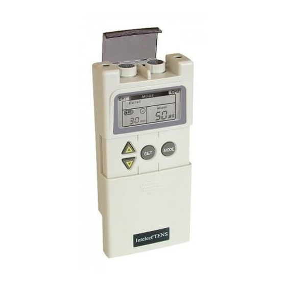
2. PRODUCT DESCRIPTIONS 2.1 Front and Rear panel: Top View Knob Cover Channel 1 On/Off and Channel 2 On/Off and Amplitude Control Amplitude Control Front View Channel 2 Output Channel 1 Output Knob Cover Receptacle Receptacle Amplitude Knob Battery Indicator Back View Mode Knob Cover... - Page 8 Knob Cover: An acrylic knob cover protects Amplitude Controls from accidental user touch when the unit is being used. After adjusting the output, remember to have the cover closed. Lid Cover: A panel covers the controls for Mode, Set, INCREASE and DECREASE adjustments. Your medical professional may ask to set these controls for you and request you leave the cover in place.
- Page 9 "DECREASE" control button (inverted triangle-button) This button decreases the pulse width from 300~50µs, decreases the pulse rate from 150 to 2Hz, and decreases the timer in continuous mode to from 90 to 5 min. "MODE" button (round-button on the right side of the control panel) This button selects a Stimulation-Mode.
-
Page 10: Stimulation Modes
3.STIMULATION MODES The Stimulation Mode button is located under the front lid cover and is adjusted by pressing the "MODE" control button. Be sure that when adjusting these stimulation modes, the intensity (amplitude) output controls are set to the minimum output positions. 3.1 BURST Mode: The burst mode provides a "burst"... - Page 11 3.3 MRW (Modulated Rate and Width) Mode: The pulse rate and width are automatically varied in a cycle to produce a pleasant, massage-like sensation. It's believed that nerves can become accustomed to, or "accommodated" to the same electrical stimulus after a period of time and thus would require increasing the intensity to further block the pain.
- Page 12 3.4 SD (Strength Duration) Mode: Strength-Duration modulation consists of alternating modulated intensity and pulse width, so the intensity is always increasing while the pulse width is decreasing and vice-versa. The stimulation intensity is modulated to 62.5% maximum of setting (width equal to setting). The pulse width is modulated to 67% of setting (intensity equal to setting).
-
Page 13: Instructions For Use
4. INSTRUCTIONS FOR USE NOTE: Always read this instruction manual before use. PREPARATION FOR USE 4.1 Check Battery: Insert a fresh 9V alkaline or rechargeable battery into the battery compartment. Make sure that you are installing the battery properly. The battery is inserted in the casing on the back of the stimulator unit. BE SURE TO MATCH THE POSITIVE AND NEGATIVE ENDS OF THE BATTERY TO THE MARKINGS IN THE BATTERY COMPARTMENT OF UNIT. -
Page 14: Connect Electrodes To Lead Wires
CONNECTING THE STIMULATOR 4.2 Connect electrodes to lead wires: Insert the lead wire connector into electrodes connector (standard 0.08 inch female connection). MAKE SURE NO BARE METAL OF THE PINS IS EXPOSED. Caution: * Always use the electrodes with the requirements of the EN60601-1 and EN60601-2, such as with CE mark, or which are legally marketed in the US under 510(K) procedure. -
Page 15: Connect Lead Wires To Unit
4.3 Connect lead wires to unit: Before proceeding to this step, be sure the unit is turned OFF. Holding the insulated portion of the lead wire connector, insert the angled-"L" plug into the receptacle on the top of the main unit. Ensure the lead wires are inserted correctly. -
Page 16: Place Electrodes On Skin
4.4 Place electrodes on skin: Apply electrodes to the exact site indicated by your physician following the instruction included with the electrodes labeling. Before applying electrodes, be sure the skin surface over which electrodes are placed is thoroughly cleaned and dried. Make sure the electrodes are placed firmly to skin and make good contact between the skin and the electrodes. -
Page 17: Select The Mode
4.6 Select the mode: Press "MODE" button to set the stimulation mode recommended by your physician or therapist. For details about stimulating waveform and sequences, please refer to Sec. 3 "Stimulation Modes". Caution: Consult physicians for your suitable stimulation mode. 4.7 Adjust the Pulse Rate: The pulses rate are adjustable 2~150Hz. -
Page 18: Adjust The Pulse Width
4.8 Adjust the Pulse Width: The pulse width is adjustable 50~300µs in 10µs increments. Press the SET button to enter the Pulse Width set function, then press INCREASE or DECREASE buttons to adjust Pulse Width to the setting recommended by your medical professional. 4.9 Adjust Timer: The timer is adjustable 5~90 minutes or continuous in 5 minute increments. - Page 19 Operation Procedure Chart: Press "MODE" button Burst Mode Adjust (1) Pulse Width (2) Timer by "SET" & " INCREASE/DECREASE" button. Press "MODE" button Normal Mode Adjust (1) Pulse Rate (2) Pulse Width (3) Timer by "SET" & " INCREASE/DECREASE" button. Press "MODE"...
-
Page 20: Turn Unit Off
4.11 Turn Unit Off: Turn both Channel Amplitude controls to OFF. Then unplug the electrode lead wires, grasping them by the plug, not the cord. If treatment will be resumed shortly, the electrodes may be left on the skin. When the electrodes are removed, clean the skin thoroughly with mild soap and water. - Page 21 Individual treatment time: Press "INCREASE" button (triangle button) or “DECREASE” button (inverted triangle button) to see next record of treatment time with the number of times or previous record of treatment time with the number of times. Press and hold Set button for 3 seconds to delete the displayed record. After the record is deleted, the unit will make a "beeping"...
- Page 22 Cumulative treatment time: When initiating the patient compliance timer, press Mode to shift the record of individual treatment time with the number of times to the record of cumulative treatment time. When showing the record of cumulative treatment time, there will be an “M”...
-
Page 23: Portability
CARE AND MAINTENANCE 4.13 Portability: Your unit is portable and may be clipped to a belt, shirt pocket, bra or other clothing. 4.14 "Low Battery" indicator: When the low power indicator flashes, the battery should be replaced with a new one as soon as possible. However, the stimulator will continue to operate for several more hours. -
Page 24: Battery
4.15 Battery: To replace the battery, remove the battery cover and extract the battery. Replace it with a 9 V alkaline or similar rechargeable battery. Make sure the battery is inserted correctly. 4.16 Care of Electrodes: To avoid skin irritation and ensure good contact with skin, clean silicone rubber electrodes with soap and water frequently. -
Page 25: Handling And Storage
5. HANDLING AND STORAGE Keep this device in the carrying case and store at room temperature. 6. SPECIFICATION Channel Dual channels, isolated between channels Pulse Amplitude 0 ~ 80mA = 0 ~ 40 Volts, adjustable (at 500 ohm load) Pulse Frequency (Hz) 2 ~ 150 Pulse Width (µs) 50 ~ 300... -
Page 26: Accessories
Stimulation Modes descriptions Mode BURST NORMAL BI-PULSE Pulse Frequency Fixed 100Hz 2~150Hz, 2~150Hz 2~150Hz Channel 1 fixed at 4Hz, Channel 2 fixed at 100Hz Pulse Width 50~300µs 50~300µs 50~300µs 50~300µs 50~300µs Cycle Time 0.5 Sec. Constant. 1 Sec. 6 Sec. 2 Sec. -
Page 27: Troubleshooting
8.TROUBLESHOOTING If your unit does not seem to be operating correctly, refer to the chart below to determine what may be wrong. If none of these measures correct the problem, the unit should be serviced. • The LCD indicator lights up but unit •... -
Page 28: Warranty
* Accessories (consisting of lead wire, AC adapter, electrodes, carrying case, and belt clip): 90 days from the date of original consumer purchase. To obtain service from Chattanooga Group or the selling dealer under this warranty, a written claim must be made within the warranty period to Chattanooga Group or the selling dealer. - Page 30 77393A 2003 Encore Medical...
Need help?
Do you have a question about the Intelect TENS and is the answer not in the manual?
Questions and answers