
Related Manuals for Chattanooga Mobile 2 RPW USA


Summary of Contents for Chattanooga Mobile 2 RPW USA
- Page 1 Mobile 2 RPW USA User Manual Operation & Installation Instructions for Mobile 2 RPW USA (Radial Pressure Wave) REF 2905-US Rx only...
-
Page 2: Table Of Contents
Mobile 2 RPW User Manual Contents 1. General Information 1.1 Introduction 1.1.1 Indications 1.1.2 Contraindications 1.1.3 Warnings and precautions 1.2 Symbols 1.3 Prerequisites for operating the device 1.3.1 Operator 1.3.2 Training of the operator 1.4 Description of controls and functional elements 1.4.1 The device 1.4.2 Compressed air supply 2. - Page 3 Mobile 2 RPW User Manual 7. Technical Specifications of the Control Device 7.1 Device 7.2 Type plate 7.3 Conformity with directives 7.4 Conformity with standards 8. R-SW handpiece Specifications and Operation 8.1 Introduction 8.2 Installing and Replacing the transmitter 8.3 Cleaning of the handpiece 8.4 Cleaning the transmitters 8.5 R-SW handpiece overhaul 8.5.1 Contents of the R-SW overhaul kit...
-
Page 4: General Information
Mobile 2 RPW User Manual 1. General Information 1.1 INTRODUCTION This manual contains warnings, safety instructions and specific operating instructions in accordance with liability regulations. DANGER Refers to a situation of acute danger which, if not avoided, could lead to serious or fatal injury. WARNING Refers to a situation of potential danger which, if not avoided, could lead to serious or fatal injury. -
Page 5: Indications
Mobile 2 RPW User Manual 1. General Information 1.1.1 INDICATIONS The device is a compact radial shock wave therapy system. Indications include: • to relieve minor muscle aches and pains. • temporary increase in local blood circulation. • activation of connective tissue. NOTE For the activation of connective tissue pressure not higher than 3bar and only D-ACTOR transmitters with a diameter of 20mm and more shall be used. -
Page 6: Symbols
1.2 SYMBOLS The markings on the Mobile 2 RPW USA system are your assurance of its conformity to the highest applicable standards of medical equipment safety and electromagnetic compatibility. One or more of the following markings may appear on the device:... -
Page 7: Prerequisites For Operating The Device
Mobile 2 RPW User Manual 1. General Information Explosion 1.3 PREREQUISITES FOR OPERATING THE DEVICE 1.3.1 OPERATOR The device is intended exclusively for use by medical specialists and may only be used by qualified and instructed medical persons. Such a specialist is expected to have practical knowledge of medical procedures and applications as well as of the terminology, and should be experienced in treating the indications stated in chapter 1.1.1. -
Page 8: Description Of Controls And Functional Elements
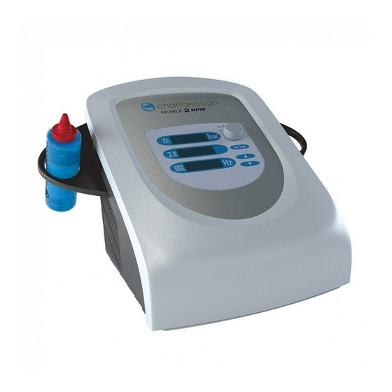
Mobile 2 RPW User Manual 1. General Information 1.4 DESCRIPTION OF CONTROLS AND FUNCTIONAL ELEMENTS 1.4.1 THE DEVICE Fig. 1 - 1 Front view of the device 1 Display of selected shock frequency 2 Treatment shock counter 3 Display of selected pressure (nominal value) 4 Shock counter reset button 5 Dial for setting the pressure 6 Handpiece... -
Page 9: Compressed Air Supply
Mobile 2 RPW User Manual 1. General Information Fig. 1 - 3 Rear view of the device 1 Type plate 2 USB connection 3 Filter housing 4 Mains connection 5 Potential equalisation connection 6 Mains fuse holder 7 Mains switch NOTE The USB connection (Fig. -
Page 10: Installation Instructions
Contact your supplier or the manufacturer immediately if any items are missing or damaged. Retain the original packaging. It may prove useful for any later equipment transport. 2.2 SCOPE OF SUPPLY The standard scope of supply of the Mobile 2 RPW USA includes the following items: • Control device •... -
Page 11: Installation
Mobile 2 RPW User Manual 2. Installation Instructions 2.3 INSTALLATION 2.3.1 HANDPIECE HOLDER INSTALLATION • The handpiece can be placed on the right or on the left side of the system. Fig. 2 - 1 Position of the handpiece holder Fig. -
Page 12: Connecting Power Supply Cables
Mobile 2 RPW User Manual 2. Installation Instructions 2.3.2 CONNECTING POWER SUPPLY CABLES • Connect the supplied mains cable to the mains connection (Fig. 2 - 3/1) on the rear of the instrument. Fig. 2 - 3 Connecting power supply cables •... -
Page 13: Handpiece Connection
Mobile 2 RPW User Manual 2. Installation Instructions 2.3.3 HANDPIECE CONNECTION • Connect the plug of the handpiece to the handpiece connection (Fig. 2 - 4/1) on the device. Fig. 2 - 4 Handpiece connection • Make sure that the red dots on the connector match the red dots on the handpiece connection (Fig. 2 - 5). Fig. -
Page 14: Operation
Mobile 2 RPW User Manual 3. Operation 3.1 GENERAL WARNINGS AND SAFETY INFORMATION CAUTION The device is intended exclusively for use by medical specialists and may only be used by such suitably qualified and trained medical personnel (see chapter 1.3 PREREQUISITES FOR OPERATING THE DEVICE). The user is responsible for correctly positioning the handpieces of the device. -
Page 15: Start-Up
Mobile 2 RPW User Manual 3. Operation NOTE The device meets the requirements of the applicable electromagnetic compatibility (EMC) standards EN 60601-1-2. These requirements are designed to provide reasonable protection against harmful interference in a typical medical installation. The instrument described here generates and uses high-frequency energy and can emit the same. If not installed and used in accordance with these instructions, the instrument may cause harmful interference with other devices in the vicinity. - Page 16 Mobile 2 RPW User Manual 3. Operation Fig. 3 - 1 Setting the energy on the control device 1 Display of selected shock frequency 2 Treatment shock counter 3 Display of selected pressure (nominal value) 4 Shock counter reset button 5 Dial for setting the pressure 6 Handpiece 7 Handpiece connector...
-
Page 17: Functional Checks
Mobile 2 RPW User Manual 3. Operation 3.3 FUNCTIONAL CHECKS Perform the following functional checks after the instrument has been installed: • Check the control device and handpiece for damage. • Put the device into operation. • Set the pressure to 1.6 bar. •... -
Page 18: Treatment
Mobile 2 RPW User Manual 3. Operation 3.5 TREATMENT CAUTION The transport bag is provided only to transport the device. If the device is left in the transport bag during treatment, the device becomes hot, due to lack of ventilation. Burns, conflagration and damages of the device are possible. -
Page 19: Info Menu
Mobile 2 RPW User Manual 3. Operation 3.6 INFO MENU The Info menu enables you to reset the handpiece counter, to call up the total shock count and instrument operating hours as well as to read out data on monitoring software, hardware serial numbers and modification status. •... -
Page 20: Cleaning, Maintenance, Overhaul
Mobile 2 RPW User Manual 4. Cleaning, Maintenance, Overhaul CAUTION Disconnect the instrument from the mains before starting any cleaning or overhaul work! 4.1 CLEANING THE INSTRUMENT • Wipe the exterior of the housing with a damp cloth. Use soapy water or a mild cleaning agent. ATTENTION It is essential that no fluid be permitted to penetrate either the instrument or its tubing. -
Page 21: Filter Replacement
Mobile 2 RPW User Manual 4. Cleaning, Maintenance, Overhaul 4.3 FILTER REPLACEMENT The filter element of the compressor should be replaced in case of compressor performance loss (marked drops in pressure during the release of shock waves or pressure pulses). Proceed as follows: •... - Page 22 Mobile 2 RPW User Manual 4. Cleaning, Maintenance, Overhaul • Remove the filter element holder from the pressure filter housing. • Ensure that both O-rings (Fig. 4-5/1 and Fig. 4-5/2) do not slip and are not misplaced. Fig. 4 - 5 Filter element holder removed •...
- Page 23 Mobile 2 RPW User Manual 4. Cleaning, Maintenance, Overhaul • Remove the top of the filter element holder. Fig. 4 - 8 Top of filter element holder removed • Remove the new filter element from its packaging. • Place the top and bottom of the holder in the new filter element and screw them together. •...
-
Page 24: Maintenance
The average expected service life (MTTF) in accordance with EN60601-1:2005 + A1:2012 is – approximately 3 500 hours for the medical - electrical device Chattanooga Mobile 2 RPW USA. For information about the service life of your handpiece, please refer to section 8.9 (Service life R-SW handpiece) and section 9.14 (Service life V-ACTOR handpiece). -
Page 25: Error Messages And Trouble-Shooting
Mobile 2 RPW User Manual 5. Error Messages and Trouble-shooting 5.1 WARNINGS The following list gives the most important error codes and the actions that you should take if they occur. Error number Fault description Corrective action Error 1 Acknowledge by pressing the reset button, Memory error continued operation is possible. -
Page 26: Trouble-Shooting
Mobile 2 RPW User Manual 5. Error Messages and Trouble-shooting 5.2 TROUBLE-SHOOTING CAUTION Unplug the mains cable from the instrument before you carry out any maintenance work! Fault description Possible cause Corrective action • Power failure • Check the power supply Instrument does not work •... -
Page 27: Technical Specifications Of The Control Device
Mobile 2 RPW User Manual 7. Technical Specifications of the Control Device 7.1 DEVICE Single shock, continuous shock 1.0 - 4.0 bar / max. 21 Hz R-SW operating mode 4.6 bar / max. 15 Hz 5.0 bar / max. 12 Hz 1.4 - 3.0 bar / max. -
Page 28: Conformity With Directives
Mobile 2 RPW User Manual 7. Technical Specifications of the Control Device 7.3 CONFORMITY WITH DIRECTIVES This medical product bears the CE mark in accordance with the Medical Device Directive (MDD) 93/42/EEC. 7.4 CONFORMITY WITH STANDARDS According to EN 60601-1 Type of protection against electric shocks: Protection class 1 Application unit of Type B*... - Page 29 Mobile 2 RPW User Manual 7. Technical Specifications of the Control Device Guidelines and manufacturer’s declaration – Resistance to emitted electromagnetic interference The device model is intended for use in the electromagnetic environment specified below. The customer or the user of the device should assure that it is used in such an environment. Emissions Electromagnetic IEC 60601 test level...
- Page 30 Mobile 2 RPW User Manual 7. Technical Specifications of the Control Device Guidelines and manufacturer’s declaration – Resistance to emitted electromagnetic interference The device model is intended for use in the electromagnetic environment specified below. The customer or the user of the device should assure that it is used in such an environment. Emissions IEC 60601 Electromagnetic...
- Page 31 Mobile 2 RPW User Manual 7. Technical Specifications of the Control Device Recommended safety distances between portable and mobile HF communications equipment and the device The device is intended for use in an electromagnetic environment in which radiated HF disturbances are controlled. The customer or the user of the device can help prevent electromagnetic interference by maintaining a minimum distance between portable and mobile HF communications equipment (transmitters) and the device as recommended below, according to the maximum output power of the communications equipment.
- Page 32 Mobile 2 RPW User Manual 7. Technical Specifications of the Control Device...
-
Page 33: R-Sw Handpiece Specifications And Operation
Mobile 2 RPW User Manual 8. R-SW handpiece Specifications and Operation 8.1 INTRODUCTION DANGER Refers to a situation of acute danger which, if not avoided, could lead to serious or fatal injury. WARNING Refers to a situation of potential danger which, if not avoided, could lead to serious or fatal injury. CAUTION Refers to a situation of potential danger which, if not avoided, could lead to minor injury. -
Page 34: Installing And Replacing The Transmitter
Mobile 2 RPW User Manual Example of a shock transmitter NOTE Pictures of handpiece and shock transmitters are examples. Individual components may differ from those shown in the illus- tration. SHOCK TRANSMITTERS Depending on the therapy to be performed, the handpiece can be equipped with different shock transmitters: 8.2 INSTALLING AND REPLACING THE TRANSMITTER The handpiece is shipped fully assembled, but if the transmitter ever requires replacement, do the following: CAUTION... - Page 35 Mobile 2 RPW User Manual 8. R-SW handpiece Specifications and Operation Component Procedure Interval Handpiece shaft and cushion clean and desinfect with usual alcohol- daily based cleaning agents and disinfectants or after 20,000 shocks (whichever comes first) Guide tube clean from inside with brush daily Transmitters and o-rings clean in ultrasound cleaning bath and...
-
Page 36: Cleaning Of The Handpiece
Mobile 2 RPW User Manual 8. R-SW handpiece Specifications and Operation • Screw the transmitter screw cap onto the handpiece until finger-tight. • After replacing the shock transmitter, make sure that the handpiece cap and the cap parts are screwed firmly in place. NOTE Make sure that the two cap parts of the D20 and the D35 shock transmitters are screwed firmly in place and that the shock transmitter screw cap is screwed firmly to the shaft. - Page 37 Mobile 2 RPW User Manual 8. R-SW handpiece Specifications and Operation • Unscrew the shaft from the handpiece and pull it out of the handpiece handle (5). • Use the supplied open-end spanner for this purpose (4). • Clean the guide tube with a brush in order to ensure perfect projectile movement. •...
-
Page 38: Cleaning The Transmitters
Mobile 2 RPW User Manual 8. R-SW handpiece Specifications and Operation 8.4 CLEANING THE TRANSMITTERS • Unscrew the shock transmitter screw cap and remove the shock transmitter insert from the shock transmitter screw cap. • Clean all of the parts under running water. NOTE The transmitter insert of the transmitters D20-S, D20-T and D35-S can only be dismantled and the sealing rings can only be removed using special tools. -
Page 39: R-Sw Handpiece Overhaul
Mobile 2 RPW User Manual 8. R-SW handpiece Specifications and Operation • Clean and disinfect the transmitter and the transmitter screw cap with the usual alcohol-based cleaning agents and disinfec- tants. • Dry the transmitter and transmitter screw cap before screwing them together. •... -
Page 40: Overhauling The Handpiece
Mobile 2 RPW User Manual 8.5.2 OVERHAULING THE HANDPIECE CAUTION Danger of injury due to shock triggering when handpiece is open. Disconnect the handpiece from the control unit before replacing the transmitter ● ATTENTION An open-end spanner should be used to release the handpiece shaft when overhauling the handpiece. •... - Page 41 Mobile 2 RPW User Manual • Dispose of the used guide tube and the used projectile. • Dispose of the detachable sealing rings of the shock transmitters and the sealing ring on the shaft. • Clean the shaft, the transmitter (including firmly seated sealing rings) and the transmit- ter screw cap with an alcohol-based disinfectant.
- Page 42 Mobile 2 RPW User Manual • Now take out of the overhaul kit the new sealing rings for the shock transmitters and for the shaft and install them. Observe the O-ring Guide for this purpose. It is contained in the overhaul kit. •...
-
Page 43: Maintenance
Mobile 2 RPW User Manual • Screw the transmitter screw cap with the required transmitter tight back onto the shaft. • Make sure that the two cap parts of the D20 and the D35 shock transmitters are scre- wed firmly in place and that the shock transmitter screw cap is screwed firmly to the shaft. -
Page 44: Trouble -Shooting
Mobile 2 RPW User Manual 8.10 TROUBLE -SHOOTING Fault description Possible cause Corrective actions No power output Leaks in handpiece cable or cable not Check the cable and tube connections properly connected and replace them, if necessary Blocked or worn projectile Dismantle the handpiece Overhaul the handpiece Handpiece defective... -
Page 45: Applicator Specifications
Mobile 2 RPW User Manual 8. R-SW handpiece Specifications and Operation 8.12 APPLICATOR SPECIFICATIONS R-SW Handpiece Technical Data Compressed Air Output 1.0 - 5 bar Frequency 1.0 - 21 Hz Ambient Air Temperature 10° C to 40° C (50° F to 104° F) Ambient temperature during operation 0°... -
Page 46: V-Actor Ii Specifications And Operation
Mobile 2 RPW User Manual 9. V-ACTOR II Specifications and Operation CAUTION Before you start using the V-ACTOR II for the first time, please make sure you have read and understood all infor- mation provided in this operating manual. Familiarity with the information and instructions contained in this manual is essential for ensuring efficient and optimal use of the instrument, for avoiding hazards to personnel and equipment and for obtaining good treatment results. -
Page 47: Scope Of Supply
Mobile 2 RPW User Manual 9. V-ACTOR II Specifications and Operation Depending on the therapy to be performed, the handpiece can be equipped with one of the following two transmitter heads: - with the V-ACTOR transmitter 25 mm (V25) - with the V-ACTOR transmitter 40 mm (V40) Fig. -
Page 48: Replacing The Transmitter
Mobile 2 RPW User Manual 9. V-ACTOR II Specifications and Operation • Gently pushing the plug into the connector will immediately lock the connection and will prevent the connector from disenga- ging automatically when the cable is pulled. • To break the connection, pull the outside of the plug body. This means the locking function is initially released, then the plug is pulled out of the socket. -
Page 49: General Warnings And Safety Information
Mobile 2 RPW User Manual 9. V-ACTOR II Specifications and Operation Fig. 9 - 6 Mount the sealing ring 9.5 GENERAL WARNINGS AND SAFETY INFORMATION CAUTION The V-ACTOR II handpiece is intended exclusively for use by medical specialists and must only be used by suitably qualified and trained medical personnel. -
Page 50: Start-Up
Mobile 2 RPW User Manual 9. V-ACTOR II Specifications and Operation 9.7 START-UP • Connect the V-ACTOR II handpiece to the control device. • Set the energy in V-ACTOR operating mode to an initial value of 2 bar. • Activate the V-ACTOR II trigger button. NOTE The trigger button functions as an on/off switch when it is pressed briefly. -
Page 51: Cleaning
Mobile 2 RPW User Manual 9. V-ACTOR II Specifications and Operation 9.11 CLEANING CAUTION Cleaning agents and disinfectants can form an explosive atmosphere. Disconnect the handpiece and the control device from the mains before starting any cleaning or maintenance work. ATTENTION Make absolutely sure that no liquid can seep into the handpiece. -
Page 52: Disposal
Mobile 2 RPW User Manual 9. V-ACTOR II Specifications and Operation V25 shock transmitter: • Unscrew the shock transmitter from the handpiece and remove the shock transmitter insert from the front cap. The spring element on the shock transmitter insert does not need to be removed. •... -
Page 53: Trouble-Shooting
Mobile 2 RPW User Manual 9. V-ACTOR II Specifications and Operation 9.15 TROUBLE-SHOOTING Fault description Possible cause Corrective action No compressed air sup- Leaks in handpiece ca- Check the cable and tube ble, or cable not prop- connections and replace erly connected them, if necessary. -
Page 54: Technical Specifications
Mobile 2 RPW User Manual 9. V-ACTOR II Specifications and Operation 9.17 TECHNICAL SPECIFICATIONS V-ACTOR ll operating frequency 1.0 - 31 Hz Energy selection in steps from 1.4 to 5 bar Ambient temperature during operation 10° – 40°C Ambient temperature during storage and transport 0°... -
Page 55: Warranty And Service
10.1 WARRANTY DJO LLC, (“Company”) warrants that the Mobile 2 RPW USA (“Product”) is free of defects in material and workmanship. This warranty shall remain in effect for two years from the date of original consumer purchase. If this Product fails to function during the two year warranty period due to a defect in material or workmanship, at the Company’s Option, Company or the selling dealer will repair or... -
Page 56: Warranty For The Handpiece
Mobile 2 RPW User Manual 10. Warranty and Service 10.2 WARRANTY FOR THE HANDPIECE Warranty claims will only be accepted if the handpiece is returned in its complete and original state, cleaned and in the case, with the repair label filled in completely. Missing components will be replaced subject to charge. - Page 57 Mobile 2 RPW User Manual...
- Page 58 DJO, LLC 1430 DECISION STREET VISTA, CA 92081 T: +1 800 494 3395 STORZ MEDICAL AG E: CHATTPRODUCTSUPPORT@DJOGLOBAL.COM Lohstampfestrasse 8 CH-8274 Tägerwilen Switzerland...
Need help?
Do you have a question about the Mobile 2 RPW USA and is the answer not in the manual?
Questions and answers