Table of Contents

Advertisement

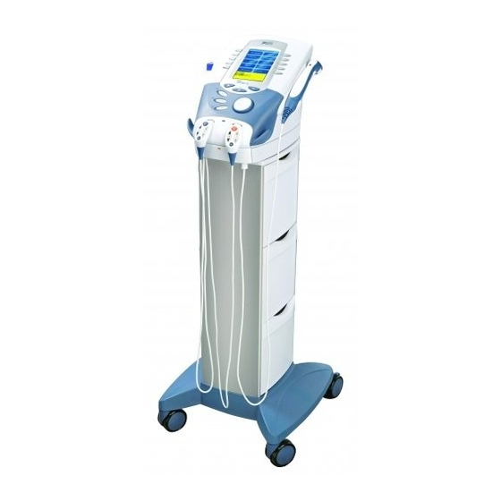
2875K- Two Channel Electrotherapy System with Cart- no sEMG
2876K- Two Channel Combination System with Cart- no sEMG
2877K- Four Channel Electrotherapy System with Cart- no sEMG
2878K- Four Channel Combination System with Cart- no sEMG
ISO 13485 CERTIFIED

User Manual

Operation & Installation
Instructions for:
Therapy Systems
2761- Two Channel Combination System
2789- Four Channel Combination System
2764- Two Channel Electrotherapy System
2787- Four Channel Electrotherapy System
2871- Two Channel Electrotherapy System- no sEMG
2872- Two Channel Combination System- no sEMG
2873- Four Channel Electrotherapy System- no sEMG
2874- Four Channel Combination System- no sEMG
Optional Equipment
2775- Therapy System Cart (Unassembled)
2775ASY- Therapy System Cart (Assembled)
2767- NiMH Battery Module
2799- Dual Channel sEMG Module
27508 and 27079- User Remote Controls
2781- Channel 3/4 Electrotherapy Module

Advertisement

Table of Contents
loading

Summary of Contents for Chattanooga 2761

  • Page 1: User Manual

    User Manual Operation & Installation Instructions for: Therapy Systems 2761- Two Channel Combination System 2789- Four Channel Combination System 2764- Two Channel Electrotherapy System 2787- Four Channel Electrotherapy System 2871- Two Channel Electrotherapy System- no sEMG 2872- Two Channel Combination System- no sEMG...
  • Page 2: Table Of Contents

    TABLE OF CONTENTS Vectra Genisys® Therapy System FOrEwOrd . . . . . . . . . . . . . . . . . . . . . . . . . . . . . . . . . . . . . . . . . . . . . . . 1 Indications- sEMG + Stim using VMS™, Symmetrical Biphasic (TENS), Asymmetrical Biphasic (TENS), or Russian waveforms .10 PrOduCT dESCriPTiON...
  • Page 3 TABLE OF CONTENTS Vectra Genisys® Therapy System System . . . . . . . . . . . . . . . . . . . . . . . . . . . . . . . . . . . . . . . . . . . . . . . . . . . . . . . . . . .17 ThErAPY SYSTEM SET uP .
  • Page 4 TABLE OF CONTENTS Vectra Genisys® Therapy System Applicator Preparation . . . . . . . . . . . . . . . . . . . . . . . . . . . . . . . . . . . . . . . . . .36 Intensity Knob Rotation .
  • Page 5 TABLE OF CONTENTS Vectra Genisys® Therapy System sEMG Screen . . . . . . . . . . . . . . . . . . . . . . . . . . . . . . . . . . . . . . . . . . . . . . . . . . . . .54 Pause Treatment .
  • Page 6 TABLE OF CONTENTS Vectra Genisys® Therapy System Prepare System and Patient . . . . . . . . . . . . . . . . . . . . . . . . . . . . . . . . . . . . .73 Add Pain Locations .
  • Page 7 TABLE OF CONTENTS Vectra Genisys® Therapy System CLiNiCAL rESOurCES LiBrArY- CLiNiCAL PrOTOCOLS™ . . . .93 Select Clinical Resources Library . . . . . . . . . . . . . . . . . . . . . . . . . . . . . . 100 Clinical Protocols™...
  • Page 8 TABLE OF CONTENTS Vectra Genisys® Therapy System CLiNiCAL rESOurCES LiBrArY- iNSTALLATiON- ChANNEL 3/4 ELECTrOThErAPY, dELETiNg SEquENCES NiMh BATTErY, ANd LASEr MOduLE . . . . . . . . . . . . . . . . . . . . . . . . . . . . . . . . . . . .108 .
  • Page 9 TABLE OF CONTENTS Vectra Genisys® Therapy System Install Lead Wires and Accessories . . . . . . . . . . . . . . . . . . . . . . . . . . . . 125 OPErATOr rEMOTE OPErATiON .
  • Page 10: Foreword

    FOrEwOrd Vectra Genisys® Therapy System This manual has been written for the users of the Vectra Genisys® Therapy Systems . It contains general information on the operation, precautionary practices, and maintenance information . In order to maximize use, efficiency, and the life of the system, please read this manual thoroughly and become familiar with the controls, as well as the accessories before operating the system .
  • Page 11: Safety Precautions

    SAFETY PrECAuTiONS Vectra Genisys® Therapy System PrECAuTiONArY dEFiNiTiONS The precautionary instructions found in this section and throughout this manual are indicated by specific symbols . Understand these symbols and their definitions before operating this equipment . The definition of these symbols are as follows: Dangerous Voltage Text with a “Dangerous Voltage”...
  • Page 12: Cautions

    . • Handle Ultrasound Applicator with care . Inappropriate handling of • Use of parts or materials other than Chattanooga's can degrade the Ultrasound Applicator may adversely affect its characteristics . minimum safety . •...
  • Page 13: Warnings

    SAFETY PrECAuTiONS Vectra Genisys® Therapy System • • U . S . A . Federal Law restricts these devices to sale by, or on the order Powered muscle stimulators should be used only with the leads and of, a physician or licensed practitioner . This device should be used electrodes recommended for use by the manufacturer .
  • Page 14: Cautions

    . • The Vectra Genisys Therapy System optional modules and associated accessories are designed for use only with the Chattanooga Vectra Genisys Electrotherapy and Combination Therapy Systems . • Remove the Ultrasound or Laser Applicator by pulling the cable...
  • Page 15: Dangers

    SAFETY PrECAuTiONS Vectra Genisys® Therapy System • Stimulus delivered by the TENS waveforms of this • NiMH Batteries contain Class E Corrosive materials . In the event of battery cell rupture or leakage, handle Battery device, in certain configurations, will deliver a charge of Module wearing neoprene or natural rubber gloves .
  • Page 16: Electrotherapy Indications, Contraindications, And Adverse Effects

    SAFETY PrECAuTiONS Vectra Genisys® Therapy System ELECTrOThErAPY iNdiCATiONS, CONTrAiNdiCATiONS, ANd AdvErSE EFFECTS Indications for VMS, VMS Burst, Russian, TENS, High Voltage Contraindications Pulsed Current (HVPC), Interferential, and Premodulated • This device should not be used for symptomatic local pain relief Waveforms unless etiology is established or unless a pain syndrome has •...
  • Page 17: Additional Precautions

    SAFETY PrECAuTiONS Vectra Genisys® Therapy System ELECTrOThErAPY iNdiCATiONS, CONTrAiNdiCATiONS, ANd AdvErSE EFFECTS (CONTiNuEd) • With TENS waveforms, isolated cases of skin irritation may Additional Precautions occur at the site of electrode placement following long-term • Caution should be used for patients with suspected or application .
  • Page 18: Emg Indications

    SAFETY PrECAuTiONS Vectra Genisys® Therapy System EMg iNdiCATiONS Indications- Surface EMG To determine the activation timing of muscles for: • Retraining of muscle activation • Coordination of muscle activation • An indication of the force produced by muscle for control and maintenance of muscle contractions •...
  • Page 19: Semg + Stim Indications, Contraindications And Adverse Effects

    SAFETY PrECAuTiONS Vectra Genisys® Therapy System sEMg + STiM iNdiCATiONS, CONTrAiNdiCATiONS ANd AdvErSE EFFECTS Indications- sEMG + Stim using VMS™, Symmetrical Biphasic Contraindications (TENS), Asymmetrical Biphasic (TENS), or Russian waveforms • This device should not be used for symptomatic local pain relief unless etiology is established or unless a pain syndrome •...
  • Page 20: Additional Precautions

    SAFETY PrECAuTiONS Vectra Genisys® Therapy System sEMg + STiM iNdiCATiONS, CONTrAiNdiCATiONS ANd AdvErSE EFFECTS (CONTiNuEd) Adverse Effects Additional Precautions • • Skin irritation and burns beneath the electrodes have been Caution should be used for patients with suspected or diagnosed reported with the use of powered muscle stimulators .
  • Page 21: Ultrasound Indications And Contraindications

    SAFETY PrECAuTiONS Vectra Genisys® Therapy System uLTrASOuNd iNdiCATiONS ANd CONTrAiNdiCATiONS Indications for Ultrasound • This device should not be used over or near bone growth Application of therapeutic deep heat for the treatment of selected centers until bone growth is complete . sub-chronic and chronic medical conditions such as: •...
  • Page 22: Nomenclature

    NOMENCLATurE Vectra Genisys® Therapy System vECTrA gENiSYS ELECTrOThErAPY ANd COMBiNATiON ThErAPY SYSTEMS Two Channel Electrotherapy System Two Channel Combination System Two Channel Combination System Two Channel Electrotherapy System (See Page 15) User Interface User Interface (See Page 15) Front Access Panel Front Access Panel Rear Access Panel Rear Access Panel...
  • Page 23: Front Access Panel

    NOMENCLATurE Vectra Genisys® Therapy System vECTrA gENiSYS ELECTrOThErAPY ANd COMBiNATiON ThErAPY SYSTEMS (CONTiNuEd) Front Access Panel Rear Access Panel Front Access Panel Lanyard NOTE: When reinstalling the Front Access Panel, make Screen Contrast Control (Not functional on Color Systems) certain the Lanyard does not become kinked . Power On/Off Switch Operator Remote Control Connector Technical Maintenance Port...
  • Page 24: User Interface

    NOMENCLATurE Vectra Genisys® Therapy System uSEr iNTErFACE (See Page 14) Rear Access Panel User Interface Ultrasound LED Coupling Indicator (Combination only) Ultrasound Applicator- 5 cm Standard . (Optional 1 cm , 2 cm and 10 cm applicators available (Combination only) Intensity Knob Cable and Lead Wire Hook (See Page 14)
  • Page 25: Symbol Definitions

    NOMENCLATurE Vectra Genisys® Therapy System SYMBOL dEFiNiTiONS Below are the definitions for all of the symbols used in the Vectra Genisys hardware and software . Study and learn these symbols before any operation of the system . System System Hardware Symbols Optional Module and Accessory Symbols Software Symbols Operator Remote...
  • Page 26: General Terminology

    NOMENCLATurE Vectra Genisys® Therapy System Below are the definitions for all of the unique terminology used throughout this manual . Study these and become familiar with these terms for ease of system operation and familiarization with the components and control functionality of the Vectra Genisys Therapy page 16 System .
  • Page 27: Specifications

    SPECiFiCATiONS Vectra Genisys® Therapy System SYSTEM SPECiFiCATiONS ANd diMENSiONS dESCriPTiON OF dEviCE MArkiNgS Width Refer to Instruction Manual/Booklet . . . . . . . . . . . . . . . . . . . . . . . . . . . . . . . . . . . . . . . . Combination System .
  • Page 28: Waveform Specifications

    SPECiFiCATiONS Vectra Genisys® Therapy System wAvEFOrM SPECiFiCATiONS IFC- Interferential (Traditional 4 Pole) TENS- Asymmetrical Biphasic Interferential Current is a medium frequency waveform . Current is The Asymmetrical Biphasic waveform has a short pulse duration . distributed through two channels (four electrodes) . The currents It is capable of strong stimulation of the nerve fibers in the skin cross each other in the body at the area requiring treatment .
  • Page 29: Tens- Symmetrical Biphasic

    SPECiFiCATiONS Vectra Genisys® Therapy System wAvEFOrM SPECiFiCATiONS (CONTiNuEd) TENS- Symmetrical Biphasic Microcurrent The Symmetrical Biphasic waveform has a short pulse duration Microcurrent is a monophasic waveform of very low intensity that and is capable of strong stimulation of nerve fibers in the skin closely simulates the electrical current generated by the human and in muscle .
  • Page 30: Ifc Premodulated (Traditional 2 Pole Ifc)

    SPECiFiCATiONS Vectra Genisys® Therapy System wAvEFOrM SPECiFiCATiONS (CONTiNuEd) Premodulated (Traditional 2 Pole IFC) High Voltage Pulsed Current (HVPC) Premodulated Current is a medium frequency waveform . Current The High Voltage Pulsed Current (HVPC) has a very brief pulse comes out of one channel (two electrodes) . The current intensity duration characterized by two distinct peaks delivered at is modulated: it increases and decreases at a regular frequency high voltage .
  • Page 31: Vms

    SPECiFiCATiONS Vectra Genisys® Therapy System wAvEFOrM SPECiFiCATiONS (CONTiNuEd) Burst VMS is a symmetrical biphasic waveform with a 100 µsec interphase interval . Because the pulse is relatively short, the waveform has a low VMS Burst is a symmetrical biphasic waveform delivered in a burst skin load, making it suitable for applications requiring high intensities, format .
  • Page 32: Russian

    SPECiFiCATiONS Vectra Genisys® Therapy System wAvEFOrM SPECiFiCATiONS (CONTiNuEd) Russian DC (Direct Current) Russian Current is a sinusoidal waveform, delivered in bursts or DC Current is a direct current flowing in one direction only . The series of pulses . This method was claimed by its author (Kots) current can be continuous or interrupted .
  • Page 33: Ultrasound Specifications

    SPECiFiCATiONS Vectra Genisys® Therapy System uLTrASOuNd SPECiFiCATiONS Ultrasound Effective Radiating Areas . . . . . . . . . . . . 10 cm Crystal: 6 . 8 cm –...
  • Page 34: Set Up

    SET uP Vectra Genisys® Therapy System vECTrA gENiSYS ThErAPY SYSTEMS Remove the Vectra Genisys Two or Four Channel Therapy System and all accessories from the shipping carton . Visually inspect for damage . Report any damage to the carrier immediately . Contents of Carton: Vectra Genisys Two or Four Channel Electrotherapy or Combination System •...
  • Page 35: Therapy System Set Up

    SET uP Vectra Genisys® Therapy System ThErAPY SYSTEM SET uP Accessing Operator Utilities Select the row of alpha or numeric SElEcT rOw anD characTEr buTTOnS characters desired by pushing the Plug unit into wall outlet . POwEr SwITch button beside the corresponding Turn system On .
  • Page 36: Restore Default Protocols

    SET uP Vectra Genisys® Therapy System ThErAPY SYSTEM SET uP (CONTiNuEd) Restore Default Protocols Restore Default Unit Settings Press Restore Default Protocols Press the Restore Default Unit rESTOrE DEfaulT rESTOrE DEfaulT unIT button . Settings button to restore the PrOTOcOlS buTTOn SETTInGS buTTOn system defaults .
  • Page 37: Erase Patient Data Card

    SET uP Vectra Genisys® Therapy System ThErAPY SYSTEM SET uP (CONTiNuEd) Erase Patient Data Card Set Date and Time Install Patient Data Card to be Press Set Date and Time button . InSErT EraSE PaTIEnT erased into Patient Data Card PaTIEnT SET DaTE carD buTTOn...
  • Page 38: Setting System Volume

    SET uP Vectra Genisys® Therapy System ThErAPY SYSTEM SET uP (CONTiNuEd) Setting System Volume Ultrasound Coupling This warning system works in conjunction with the Applicator Press Volume button until vOluME LED to alert the user should the Sound Head become uncoupled the desired system volume is buTTOn from the patient .
  • Page 39: Display Unit Version Information

    SET uP Vectra Genisys® Therapy System ThErAPY SYSTEM SET uP (CONTiNuEd) Display Unit Version Information Pad Contact Quality The Pad Contact Quality feature indicates to the user the contact Press the Display Unit Version PrESS DISPlay unIT quality of the electrodes on the patient . This function, if On, Information button to show vErSIOn buTTOn TO vIEw displays a bar graph at the bottom of Treatment Review screen for...
  • Page 40: Select Language

    SET uP Vectra Genisys® Therapy System ThErAPY SYSTEM SET uP (CONTiNuEd) Select Language Connecting Accessories to the Therapy System To change the language Install Lead Wires, Ultrasound Applicator, Patient Interrupt Switch lanGuaGE displayed on the system, press and any other accessories according to the Front Access Panel as buTTOn the Language button until the page 16...
  • Page 41: Patient Preparation

    PATiENT PrEPArATiON Vectra Genisys® Therapy System ELECTrOThErAPY PATiENT PrEPArATiON Electrode Placement Examine the skin for any wounds and clean the skin . • Apply the electrodes to the treatment area . • Ensure the electrodes are applied securely to the skin . •...
  • Page 42: Dura-Stick™ Electrodes

    Reusable Carbon Electrodes (Optional) Chattanooga DURA-STICK Electrodes are a self adhesive, If used for delivery of electrotherapy, the Carbon Electrodes disposable product designed specifically for use with Chattanooga must be used with a conductive medium such as Conductor™ Electrotherapy systems .
  • Page 43: Dura-Stick™ Electrode Instructions

    PATiENT PrEPArATiON Vectra Genisys® Therapy System ELECTrOThErAPY PATiENT PrEPArATiON (CONTiNuEd) DURA-STICK™ Electrode Instructions Connecting Lead Wires Securing Electrodes Remove the DURA-STICK Electrodes from Insert the lead with the Red (+) electrode lEaD wIrE SEaTED the protective backing and apply to the connector into one DURA-STICK Electrode .
  • Page 44: Reusable Carbon Electrodes (Optional)

    PATiENT PrEPArATiON Vectra Genisys® Therapy System ELECTrOThErAPY PATiENT PrEPArATiON (CONTiNuEd) Reusable Carbon Electrodes (Optional) Conductive Medium Securing Electrodes Connecting Lead Wires Insert the lead with the Red (+) electrode Liberally apply Conductor™ Transmission Use Nylatex Wrap to secure each electrode ®...
  • Page 45: Ultrasound Patient Preparation

    PATiENT PrEPArATiON Vectra Genisys® Therapy System uLTrASOuNd PATiENT PrEPArATiON Preparing Treatment Area Conductive Medium Examine the skin for any wounds and clean the skin . Liberally apply Conductor™ aPPly Transmission Gel or equivalent to Size of Applicator cOnDucTIvE GEl the treatment area on the patient . View the Sound Head Recommendation in the Treatment Review screen for Ultrasound (as a reference point only) prior to administering treatment .
  • Page 46: Semg And Semg+Stim Patient Preparation

    Install sEMG Lead Wires to System PrESS EMG Or EMG+STIM buTTOn Chattanooga equipment and will provide Remove the Front Access Cover from the an accurate reading of sEMG activity . Therapy System and remove the existing Leave electrodes on the protective Lead Wires .
  • Page 47: Select Body Area

    PATiENT PrEPArATiON Vectra Genisys® Therapy System EMg ANd EMg+STiM PATiENT PrEPArATiON (CONTiNuEd) Select Body Area View Electrode Placement Graphic Press the Electrode Placement button to Press the Up and Down Arrow buttons Press the Accept and Return Arrow button view the Select Body Area screen . until the area desired is highlighted .
  • Page 48: View Electrode Placement Text

    PATiENT PrEPArATiON Vectra Genisys® Therapy System EMg ANd EMg+STiM PATiENT PrEPArATiON (CONTiNuEd) View Electrode Placement Text Prepare Treatment Area Examine the skin for any wounds . Press the Next Page button to view Press the Next Page button to view text relating to the specific electrode additional text .
  • Page 49: Electrode Placement

    PATiENT PrEPArATiON Vectra Genisys® Therapy System EMg ANd EMg+STiM PATiENT PrEPArATiON (CONTiNuEd) Intra-Vaginal Probe Electrode Placement NOTE: The electrodes may be placed Using DURA-STICK™ II 1 . 2 5 in (3 cm) If using the Intra-Vaginal Probe, plug the for specific, general and electrodes, place the Active (red and active ends of the sEMG lead wire (red and quasi-specific biofeedback muscle...
  • Page 50: Operation

    OPErATiON Vectra Genisys® Therapy System OPErATOr iNTErFACE The Vectra Genisys Therapy System Operator Interface houses all of the functions and controls necessary for the operator to access all operator utilities, modalities and parameters for modification and system set up . Clinical Resources Library button Top of Screen Used to access Clinical Protocols™, User...
  • Page 51: Home Screen

    OPErATiON Vectra Genisys® Therapy System hOME SCrEEN The Vectra Genisys Home screen affords access to all of the system modalities and functions . The area surrounding the screen has 10 modality and parameter modification buttons . Electrotherapy Accesses all the available waveforms and parameter editing controls . Indications Accesses specific pre-programmed indications, for general reference only, which aid in selecting the proper waveform and electrode placement for particular...
  • Page 52: Electrotherapy Screen

    OPErATiON Vectra Genisys® Therapy System ELECTrOThErAPY SCrEEN The screen allows the operator to access, set up, and modify parameters of each of the available waveforms within the Vectra Genisys Therapy System . The following pages give a general explanation of a treatment setup . page Refer to the Specifications section, beginning on for detailed specifications of the system and each available...
  • Page 53: General Electrotherapy Waveform Set Up

    OPErATiON Vectra Genisys® Therapy System gENErAL ELECTrOThErAPY wAvEFOrM SET uP The following information is an example of step by step set up for the Electrotherapy waveforms . All waveforms in the Vectra Genisys Therapy System are set up and edited in the same basic fashion . The following set up instructions use Interferential Waveform . Prepare Patient Select Waveform View Waveform Description...
  • Page 54: View Electrode Placement

    OPErATiON Vectra Genisys® Therapy System gENErAL ELECTrOThErAPY wAvEFOrM SET uP (CONTiNuEd) View Electrode Placement Edit Waveform Parameters Install Optional Patient Interrupt Switch Press the Electrode Placement button to Press Edit button to access waveform Make certain the Patient Interrupt Switch is view the most commonly used electrode parameters .
  • Page 55: Optional Patient Interrupt Switch

    OPErATiON Vectra Genisys® Therapy System gENErAL ELECTrOThErAPY wAvEFOrM SET uP (CONTiNuEd) Optional Patient Interrupt Switch Set Waveform Intensity Start Treatment Give Patient Interrupt Switch to patient Set intensity by rotating the Intensity Control Press the Start button to begin therapy and explain that pressing the Red button Knob to the prescribed level .
  • Page 56: Pause Treatment

    OPErATiON Vectra Genisys® Therapy System gENErAL ELECTrOThErAPY wAvEFOrM SET uP (CONTiNuEd) Save to Patient Data Card Pause Treatment Stop Treatment Press the Pause button to pause therapy To Stop treatment, press the Stop button After session is complete, press the Save session and maintain remaining time .
  • Page 57: Adjusting Electrotherapy Channel Parameters During Treatment

    OPErATiON Vectra Genisys® Therapy System AdjuSTiNg ELECTrOThErAPY ChANNEL PArAMETErS duriNg TrEATMENT The Electrotherapy channel parameters may be changed during a treatment session without pausing or stopping the treatment . The waveform Intensity may be increased or decreased at any time during the session without utilizing this process . Select Channel Edit Channel Paramenters Press the Edit button .
  • Page 58: Ultrasound

    . treatment area . NOTE: Use only Vectra Genisys ParaMETEr raTIOnalE Ultrasound Applicators . Previous buTTOn SOunD hEaD models of Chattanooga Ultrasound rEcOMMEnDaTIOn Applicators will not work with the buTTOn nExT Vectra Genisys Therapy System . PaGE buTTOn...
  • Page 59: Edit Ultrasound Parameters

    OPErATiON Vectra Genisys® Therapy System uLTrASOuNd (CONTiNuEd) Edit Ultrasound Parameters Head Warming Set Ultrasound Intensity Press Edit button to access ultrasound The Vectra Genisys Therapy System Set intensity by rotating the Intensity Control parameters . incorporates a Head Warming feature that Knob to the prescribed level .
  • Page 60: Start Treatment

    OPErATiON Vectra Genisys® Therapy System uLTrASOuNd (CONTiNuEd) Start Treatment Pause Treatment Stop Treatment Press the Start button to begin therapy Press the Pause button to pause therapy To Stop treatment, press the Stop button session . session and maintain remaining time . To once .
  • Page 61: Adjusting Ultrasound Parameters During Treatment

    OPErATiON Vectra Genisys® Therapy System AdjuSTiNg uLTrASOuNd PArAMETErS duriNg TrEATMENT The ultrasound parameters may be changed during a treatment session without pausing or stopping the treatment . The following information provides instructions for changing ultrasound treatment parameters during a treatment session . The ultrasound intensity may be increased or decreased at any time during the session without utilizing this process .
  • Page 62: Emg Therapy Set Up

    OPErATiON Vectra Genisys® Therapy System EMg ThErAPY SET uP General Information The Vectra Genisys sEMG modality reads and records the sEMG biofeedback activity of a muscle or muscle group by sensing the electrical impulses generated during a voluntary muscle contraction and relax cycle . These signals are accurately relayed to the Vectra Genisys Therapy System through 1 .
  • Page 63: Semg Screen

    OPErATiON Vectra Genisys® Therapy System EMg ThErAPY SET uP (CONTiNuEd) sEMG Screen The Vectra Genisys sEMG screen affords access to all of the sEMG parameters and functions . The area surrounding the screen has 10 parameter modification buttons . However, only six are used for the sEMG modality . Below is a general description of each of the sEMG parameter buttons .
  • Page 64: Prepare System And Patient

    OPErATiON Vectra Genisys® Therapy System EMg ThErAPY SET uP (CONTiNuEd) Prepare System and Patient View sEMG Description Text Prepare Therapy System and patient . Refer Press the sEMG Description Text button to Press the Next Page button to view pages 37 through 40 .
  • Page 65: Select Edit

    OPErATiON Vectra Genisys® Therapy System EMg ThErAPY SET uP (CONTiNuEd) Select Edit Select Channel Set Alarm Set the alarm trigger in relation to the Press the Edit button on the Treatment Press the Channel Button until the target by pressing the Alarm button until Review screen to edit sEMG parameters as prescribed channel is displayed in the icon .
  • Page 66: Set Audio Type

    OPErATiON Vectra Genisys® Therapy System EMg ThErAPY SET uP (CONTiNuEd) Set Audio Type Select Target Option Setting Max Target Audio sets the type of sound heard when Three options are available for setting the Make certain Target Max is displayed in the the muscle contraction reaches the Alarm sEMG modality target: Target icon .
  • Page 67: Setting Avg Target

    OPErATiON Vectra Genisys® Therapy System EMg ThErAPY SET uP (CONTiNuEd) Setting Avg Target Make certain Target Avg is displayed in the During the preset 15 second contraction During the preset 10 second contraction Target icon . period, the Therapy System captures and period, the Therapy System captures retains the average maximum level of the and retains the maximum level of the...
  • Page 68: Setting Manual Target

    OPErATiON Vectra Genisys® Therapy System EMg ThErAPY SET uP (CONTiNuEd) Setting Manual Target Set Volume Make certain Target Manual is displayed in Press the Up and Down Arrow buttons to Press Volume button until the desired the Target icon . adjust Target to prescribed level .
  • Page 69: Start Semg Therapy Session

    OPErATiON Vectra Genisys® Therapy System EMg ThErAPY SET uP (CONTiNuEd) Start sEMG Therapy Session Stopping sEMG Therapy Session Have patient perform contractions as Press the Stop Button . The Completed NOTE: To record the sEMG Data to a sEMG prescribed . Data Card, refer to the sEMG Data Treatment Review Screen will display .
  • Page 70: Indications

    OPErATiON Vectra Genisys® Therapy System iNdiCATiONS The Vectra Genisys Therapy System incorporates a unique Indications section which allows the user to select specific Clinical Indications and apply the most common therapy for the Indication selected . All modalities are editable, in their normal editing fashion, in order to customize the treatment for each patient’s prescribed therapy .
  • Page 71: View Electrode Placement

    OPErATiON Vectra Genisys® Therapy System iNdiCATiONS (CONTiNuEd) View Electrode Placement Install Optional Patient Interrupt Switch Edit Waveform Parameters Press the Electrode Placement button to Make certain the Patient Interrupt Switch is Press Edit button to access waveform view the most commonly used electrode connected to the unit .
  • Page 72: Optional Patient Interrupt Switch

    OPErATiON Vectra Genisys® Therapy System iNdiCATiONS (CONTiNuEd) Optional Patient Interrupt Switch Setting Waveform Intensity Give Patient Interrupt Switch to patient Reset intensity and press the Start button Set intensity by rotating the Intensity Control and explain that pressing the Red button to resume session .
  • Page 73: Start Treatment

    OPErATiON Vectra Genisys® Therapy System iNdiCATiONS (CONTiNuEd) Pause Treatment Stop Treatment Start Treatment Press the Start button to begin therapy Press the Pause button to pause therapy To Stop treatment, press the Stop button session . session and maintain remaining time . To once .
  • Page 74: Editing Parameters During Treatment Session

    OPErATiON Vectra Genisys® Therapy System iNdiCATiONS (CONTiNuEd) Editing Parameters during Treatment Save to Patient Data Card Session After session is complete, press the Save Refer to pages 80 The parameters may be edited during to Patient Card button . through 89 a treatment session without pausing or for Patient Data Card Setup stopping the treatment .
  • Page 75: Combination

    OPErATiON Vectra Genisys® Therapy System COMBiNATiON The Vectra Genisys Therapy System Combination modality allows the user to select and use ultrasound therapy in combination with electrical muscle stimulation . Combination therapy utilizes the Ultrasound modality in conjuction with High Voltage Pulsed Current (HVPC), IFC (4p), IFC Premodulated (2p), Asymmetrical Biphasic, Symmetrical Biphasic or VMS to generate a therapeutic effect .
  • Page 76: View Electrode Placement

    OPErATiON Vectra Genisys® Therapy System COMBiNATiON (CONTiNuEd) View Electrode Placement Access Combination Parameters Edit Ultrasound Parameters Press the Electrode Placement button to Press Edit button to access Combination Press the corresponding button to edit view the most commonly used electrode parameters .
  • Page 77: Select Waveform

    OPErATiON Vectra Genisys® Therapy System COMBiNATiON (CONTiNuEd) Select Waveform Optional Patient Interrupt Switch Edit Waveform Parameters Connect Patient Interrupt Switch to the Press the Edit Stim button to edit the Press the Select Waveform button . Therapy System . Give Patient Interrupt parameters of the waveform selected .
  • Page 78: Set Waveform Intensity

    OPErATiON Vectra Genisys® Therapy System COMBiNATiON (CONTiNuEd) Set Waveform Intensity Set Ultrasound Intensity Start Treatment Set intensity by rotating the Intensity Control Press the Edit Ultrasound button . Press the Start button to begin therapy Knob to the prescribed level . Set Ultrasound intensity by rotating the session .
  • Page 79: Pause Treatment

    OPErATiON Vectra Genisys® Therapy System COMBiNATiON (CONTiNuEd) Pause Treatment Stop Treatment Save to Patient Data Card After session is complete, press the Save Press the Pause button to pause therapy To Stop treatment, press the Stop button pages 80 to Patient Card button . Refer to session and maintain remaining time .
  • Page 80: Adjusting Combination Parameters During Treatment

    OPErATiON Vectra Genisys® Therapy System AdjuSTiNg COMBiNATiON PArAMETErS duriNg TrEATMENT The channel parameters may be changed during a treatment session without pausing or stopping the treatment . The following information provides instructions for changing Combination Treatment Electrotherapy Channel and Ultrasound parameters during a treatment session .
  • Page 81: Emg+Stim Therapy Set Up

    OPErATiON Vectra Genisys® Therapy System EMg+STiM ThErAPY SET uP General Information The Vectra Genisys sEMG + Stim modality utilizes sEMG biofeedback activity coupled with triggered electrical muscle stimulation using selected electrotherapy waveforms for the maximum benefit in muscle retraining . The sEMG + Stim will not function as a multi-channel modality .
  • Page 82: Prepare System And Patient

    OPErATiON Vectra Genisys® Therapy System EMg+STiM ThErAPY SET uP (CONTiNuEd) Prepare System and Patient Select Edit Select Channel Prepare Therapy System and patient . Refer Press the Edit button on the Treatment Press the Channel button until the pages 37 through 40 .
  • Page 83: Set Alarm

    OPErATiON Vectra Genisys® Therapy System EMg + STiM ThErAPY SET uP (CONTiNuEd) Set Alarm Set Audio Type Select Stim Waveform Audio sets the type of sound heard when Press the Stim button . Set the alarm trigger in relation to the the muscle contraction reaches the Alarm target by pressing the Alarm button until STIM...
  • Page 84: Edit Stim

    OPErATiON Vectra Genisys® Therapy System EMg + STiM ThErAPY SET uP (CONTiNuEd) Edit Stim Select Target Option Setting Max Target Press the Edit Stim button . Three options are available for setting the Make certain Target Max is displayed in the sEMG modality target: Target icon .
  • Page 85: Setting Avg Target

    OPErATiON Vectra Genisys® Therapy System EMg + STiM ThErAPY SET uP (CONTiNuEd) Setting Avg Target Make certain Target Avg is displayed in the During the preset 15 second contraction During the preset 10 second contraction Target icon . period, the Therapy System captures and period, the Therapy System captures retains the average maximum level of the and retains the maximum level of the...
  • Page 86: Setting Manual Target

    OPErATiON Vectra Genisys® Therapy System EMg + STiM ThErAPY SET uP (CONTiNuEd) Set Volume Setting Manual Target Press Volume button until the desired Make certain Target Manual is displayed in Press the Up and Down Arrow buttons to volume level is displayed in the Volume the Target icon .
  • Page 87: Set Auto Feature

    OPErATiON Vectra Genisys® Therapy System EMg + STiM ThErAPY SET uP (CONTiNuEd) Set Auto Feature Start sEMG Therapy Session The sEMG + Stim Auto feature is designed After all parameters for sEMG and Stim have Have patient perform contractions as to work in conjunction with the Target been completed, press the Start sEMG + prescribed .
  • Page 88: Stopping Stim

    OPErATiON Vectra Genisys® Therapy System EMg + STiM ThErAPY SET uP (CONTiNuEd) Stopping Stim Stopping Therapy Session After Stim is complete, the screen will Stim may be stopped at any time during Press the Stop button . The Completed change and the patient should relax the the session by pressing the Stop sEMG + Treatment Review screen will display .
  • Page 89: Patient Data Card- Set Up Of New Card

    OPErATiON Vectra Genisys® Therapy System PATiENT dATA CArd- SET uP OF NEw CArd General Information The Vectra Genisys Therapy System incorporates a Patient Data Card reading and recording device that allows transfer of patient therapy data from the system to the card for reviewing patient modality and pain profile information . Information may be transferred to a PC via the optional Patient Data Management System .
  • Page 90: Enter Patient Id

    OPErATiON Vectra Genisys® Therapy System PATiENT dATA CArd- SET uP OF NEw CArd (CONTiNuEd) Enter Patient ID Select the row of alpha or numeric When the desired character is framed, press To delete a character, press the Left Arrow characters desired by pushing the button the Accept and Return Arrow button .
  • Page 91: Access Electrode Placement

    OPErATiON Vectra Genisys® Therapy System PATiENT dATA CArd- SET uP OF NEw CArd (CONTiNuEd) Electrode Placement Set Up Access Electrode Placement Electrode Placement Press the Pad button to select the Red (+) or The following information uses an IFC Press the Up, Down, Left and Right Arrow Black (-) electrode .
  • Page 92: Access Pain Map

    OPErATiON Vectra Genisys® Therapy System PATiENT dATA CArd- SET uP OF NEw CArd (CONTiNuEd) Access Pain Map Select Pain Type Add Pain Locations Press the Pain Map button to select Press the Pain Type button until the Press the Add button . The Add Pain Map the body area of the associated pain as desired description is displayed in the Pain window will display .
  • Page 93: Select Location Of Pain

    OPErATiON Vectra Genisys® Therapy System PATiENT dATA CArd- SET uP OF NEw CArd (CONTiNuEd) Editing Pain Locations Select Location of Pain Press the Add button to continue selecting, Press the Up and Down Arrow buttons to Press the Edit button on the Pain Map in sequence, the radiating path of the pain move the Pain Locator to the area of the window .
  • Page 94: Deleting Pain Locations

    OPErATiON Vectra Genisys® Therapy System PATiENT dATA CArd- SET uP OF NEw CArd (CONTiNuEd) Pain Scales Deleting Pain Locations The Vectra Genisys Therapy System incorporates two internationally recognized Pain Press the Delete button on the Pain Map Scales: one, VAS (Visual Analog Scale) has no indicator marks and, two, Numeric Scale window .
  • Page 95: Save To Patient Data Card

    OPErATiON Vectra Genisys® Therapy System PATiENT dATA CArd- SET uP OF NEw CArd (CONTiNuEd) Save to Patient Data Card Press the Home button . After all desired session data has been entered in the Patient Data Card screens, Remove the Patient Data Card for filing with press the Save to Patient Card button .
  • Page 96: Existing Patient Data Card Use

    OPErATiON Vectra Genisys® Therapy System ExiSTiNg PATiENT dATA CArd uSE Insert Existing Patient Data Card Access Patient Data Card View Patient Data Card Insert the Patient Data Card assigned to the Press the Patient Card button to access Press the corresponding button beside the patient receiving treatment into the system Patient Data Card .
  • Page 97: Starting A New Treatment From Patient Data Card

    OPErATiON Vectra Genisys® Therapy System ExiSTiNg PATiENT dATA CArd uSE (CONTiNuEd) Starting a New Treatment from Patient Optional Patient Interrupt Switch Set Intensity Data Card Connect Patient Interrupt Switch to the Set intensity by rotating the Intensity Control pages 32-35 Therapy System .
  • Page 98: Start Treatment

    OPErATiON Vectra Genisys® Therapy System ExiSTiNg PATiENT dATA CArd uSE (CONTiNuEd) Pause Treatment Stop Treatment Start Treatment Press the Start button to begin therapy Press the Pause button to pause therapy To Stop treatment, press the Stop button session . session and maintain remaining time .
  • Page 99: Set Up Of New Semg Data Card

    OPErATiON Vectra Genisys® Therapy System SET uP OF NEw sEMg dATA CArd General Information The Vectra Genisys Therapy System incorporates a sEMG Data Card that allows the recording of sEMG data from sEMG therapy sessions . After recording the sEMG data, it can be imported, saved to, and viewed through a Windows® PC equipped with the optional Patient Data Management System .
  • Page 100: Insert New Semg Data Card

    OPErATiON Vectra Genisys® Therapy System SET uP OF NEw sEMg dATA CArd (CONTiNuEd) Insert New sEMG Data Card Set Up sEMG Therapy Session Enter Patient ID Insert a new sEMG Data Card into the Set up the patient's prescribed sEMG Select the row of alpha or numeric pages 53 characters by pushing the button beside...
  • Page 101: Begin Save

    OPErATiON Vectra Genisys® Therapy System SET uP OF NEw sEMg dATA CArd (CONTiNuEd) Begin Save When the desired character is framed, press To delete a character, press the Left Arrow Press the Begin Save button . A message will the Accept and Return Arrow button . The button until the character to delete is appear verifying that sEMG data is being character selected will display in the top of...
  • Page 102: Clinical Resources Library- Clinical Protocols

    OPErATiON Vectra Genisys® Therapy System CLiNiCAL rESOurCES LiBrArY- CLiNiCAL PrOTOCOLS™ The Vectra Genisys Clinical Resources Library contains Clinical Protocols™, User Protocols, Sequencing functions, and access to the Multimedia Card (MMC) which contains the Anatomical and Pathological Libraries . Clinical Protocols™ This library is a series of protocol presets where the Body Area, Clinical Indication, Pathological Condition and Pathological Severity are selected by the user, and the Clinical Protocols algorithm will select the parameter settings .
  • Page 103: Select Clinical Indication

    OPErATiON Vectra Genisys® Therapy System CLiNiCAL rESOurCES LiBrArY- CLiNiCAL PrOTOCOLS™ (CONTiNuEd) Select Clinical Indication Select Pathological Condition Select Pathological Severity Press the button beside the desired Press the button beside the Clinical Press the button beside the desired Pathological Condition . Protocol desired in either the Electrotherapy Pathological Condition .
  • Page 104: View Waveform Rationale

    OPErATiON Vectra Genisys® Therapy System CLiNiCAL rESOurCES LiBrArY- CLiNiCAL PrOTOCOLS™ (CONTiNuEd) View Waveform Rationale View Electrode Placement Prepare Patient pages 32 through 35 Press the Electrode Placement button to Refer to Press the Waveform Rationale button page 36 view the specific electrode placement for Electrotherapy, and for Ultrasound, (Electrotherapy Modalities) or the Parameter...
  • Page 105: Optional Patient Interrupt Switch

    OPErATiON Vectra Genisys® Therapy System CLiNiCAL rESOurCES LiBrArY- CLiNiCAL PrOTOCOLS™ (CONTiNuEd) Optional Patient Interrupt Switch Set Modality Intensity Make certain the Patient Interrupt Switch, Set intensity by rotating the Intensity Control Give Patient Interrupt Switch to patient for the channel(s) being used, is connected Knob to the prescribed level .
  • Page 106: Start Treatment

    OPErATiON Vectra Genisys® Therapy System CLiNiCAL rESOurCES LiBrArY- CLiNiCAL PrOTOCOLS™ (CONTiNuEd) Start Treatment Pause Treatment Stop Treatment Press the Start button to begin therapy Press the Pause button to pause therapy To Stop treatment, press the Stop button session . session and maintain remaining time .
  • Page 107: Clinical Resources Library- Creating User Protocols

    OPErATiON Vectra Genisys® Therapy System CLiNiCAL rESOurCES LiBrArY- CrEATiNg uSEr PrOTOCOLS General Information This library is a series of protocols created by the user and stored in the system memory . The following information gives general instructions as to setting up, saving, and accessing User Protocols . Should the Default Protocols be restored, through the User Utilities, all User Protocols will be permanently removed from the system .
  • Page 108: Enter User Protocol Name

    OPErATiON Vectra Genisys® Therapy System CLiNiCAL rESOurCES LiBrArY- CrEATiNg uSEr PrOTOCOLS (CONTiNuEd) Enter User Protocol Name Select the row of alpha or numeric When the desired character is framed, press To delete a character, press the Left Arrow characters desired by pushing the button the Accept and Return Arrow button .
  • Page 109: Clinical Resources Library- Deleting User Protocols

    OPErATiON Vectra Genisys® Therapy System CLiNiCAL rESOurCES LiBrArY- dELETiNg uSEr PrOTOCOLS General Information The following information provides instructions for the deletion of one User Protocol at a time . Once any single User Protocol is deleted, it cannot be recovered . Should the Default Protocols be restored through the User Utilities, all User Protocols will be permanently removed from the system .
  • Page 110: Clinical Resources Library- Using User Protocols

    OPErATiON Vectra Genisys® Therapy System CLiNiCAL rESOurCES LiBrArY- uSiNg uSEr PrOTOCOLS Access User Protocols Select User Protocol View Waveform Rationale Press the Clinical Resources Library button . Press the Waveform Rationale button Press the UP and Down Arrow buttons until the Press the User Protocols button .
  • Page 111: View Electrode Placement

    OPErATiON Vectra Genisys® Therapy System CLiNiCAL rESOurCES LiBrArY- uSiNg uSEr PrOTOCOLS (CONTiNuEd) View Electrode Placement Prepare Patient Optional Patient Interrupt Switch pages 32 through 35 Press the Electrode Placement button to Refer to Make certain the Patient Interrupt Switch, page 36 view the electrode placement for the User Electrotherapy and for Ultrasound...
  • Page 112: Set Modality Intensity

    OPErATiON Vectra Genisys® Therapy System CLiNiCAL rESOurCES LiBrArY- uSiNg uSEr PrOTOCOLS (CONTiNuEd) Set Modality Intensity Start Treatment Set intensity by rotating the Intensity Control Give Patient Interrupt Switch to patient Press the Start button to begin therapy Knob to the prescribed level . and explain that pressing the Red button session .
  • Page 113: Pause Treatment

    OPErATiON Vectra Genisys® Therapy System CLiNiCAL rESOurCES LiBrArY- uSiNg uSEr PrOTOCOLS (CONTiNuEd) Pause Treatment Stop Treatment Save to Patient Data Card Press the Pause button to pause therapy To Stop treatment, press the Stop button After session is complete, press the Save session and maintain remaining time .
  • Page 114: Clinical Resources Library- Creating New Sequences

    OPErATiON Vectra Genisys® Therapy System CLiNiCAL rESOurCES LiBrArY- CrEATiNg NEw SEquENCES General Information This Library is a series of Electrotherapy Waveform/Current Sequences created by the user for special electrotherapy treatment purposes and stored in the system memory for recall and use . The following information gives general instructions for setting up, saving and accessing of sequences .
  • Page 115: Edit First Waveform Or Current

    OPErATiON Vectra Genisys® Therapy System CLiNiCAL rESOurCES LiBrArY- CrEATiNg NEw SEquENCES (CONTiNuEd) Edit First Waveform or Current Select Second Waveform or Current Saving New Sequence Press the Edit button on the Sequence Press the Down Arrow button on the After all waveforms/currents have been screen .
  • Page 116: Enter Sequence Name

    OPErATiON Vectra Genisys® Therapy System CLiNiCAL rESOurCES LiBrArY- CrEATiNg NEw SEquENCES (CONTiNuEd) Enter Sequence Name Select the row of alpha or numeric When the desired character is framed, press To delete a character, press the Left Arrow characters desired by pushing the button the Accept and Return Arrow button .
  • Page 117: Clinical Resources Library- Deleting Sequences

    OPErATiON Vectra Genisys® Therapy System CLiNiCAL rESOurCES LiBrArY- dELETiNg SEquENCES General Information The following information provides instructions for the deletion of one user defined sequence at a time . Once any single sequence is deleted, it cannot be recovered . Should the Default Protocols be restored through the User Utilities, all user defined sequences will be permanently removed from the system .
  • Page 118: Clinical Resources Library- Using Sequences

    OPErATiON Vectra Genisys® Therapy System CLiNiCAL rESOurCES LiBrArY- uSiNg SEquENCES Access Sequencing Select Sequence Select Waveform/Current Press the Clinical Resources Library button . Press the UP and Down Arrow buttons until the Press the Down Arrow button on the Press the Sequencing button . prescribed Sequence is highlighted .
  • Page 119: View Waveform Rationale

    OPErATiON Vectra Genisys® Therapy System CLiNiCAL rESOurCES LiBrArY- uSiNg SEquENCES (CONTiNuEd) View Waveform Rationale View Electrode Placement Prepare Patient pages 32 through 35 Press the Waveform Description button to Press the Electrode Placement button Refer to view the text explaining the rationale for to view the electrode placement for the Electrotherapy patient preparation Sequence selected .
  • Page 120: Set Sequence Intensity

    OPErATiON Vectra Genisys® Therapy System CLiNiCAL rESOurCES LiBrArY- uSiNg SEquENCES (CONTiNuEd) Set Sequence Intensity The first waveform/current in the Sequence Press the Down Arrow button until the Give Patient Interrupt Switch to patient should be highlighted . Set intensity by second waveform/current in the sequence is and explain that pressing the Red button rotating the Intensity Control Knob to the...
  • Page 121: Start Treatment

    OPErATiON Vectra Genisys® Therapy System CLiNiCAL rESOurCES LiBrArY- uSiNg SEquENCES (CONTiNuEd) Pause Treatment Stop Treatment Start Treatment Press the Pause button to pause therapy Press the Start button to begin therapy To Stop treatment, press the Stop button session and maintain remaining time . To session .
  • Page 122: Clinical Resources Library- Mmc Graphical Library

    OPErATiON OPErATiON Vectra Genisys® Therapy System CLiNiCAL rESOurCES LiBrArY- MMC grAPhiCAL LiBrArY General Information The Clinical Resources Library contains the unique Anatomical and Pathological Graphic Libraries* from DJO, LLC . These Graphic Libraries are contained on a single Multimedia Card (MMC) and are designed to aid the operator in visually understanding and locating specific muscle groups and commonly found problems associated with Pathological Conditions as well as providing an educational tool for the clinician to use with the patient .
  • Page 123: Select Library Type

    OPErATiON OPErATiON Vectra Genisys® Therapy System CLiNiCAL rESOurCES LiBrArY- MMC grAPhiCAL LiBrArY (CONTiNuEd) Select Library Type Select the desired graphic by pressing the Anatomical Example- Muscles Pathological Example- Rotator Cuff Tear corresponding button . Superficial Left Side buttons- Anatomical Selections Right Side buttons- Pathological Selections anaTOMIcal...
  • Page 124: Installation/Removal

    iNSTALLATiON/rEMOvAL Vectra Genisys® Therapy System iNSTALLATiON- ChANNEL 3/4 ELECTrOThErAPY, NiMh BATTErY, ANd LASEr MOduLE Possible System Configurations The Vectra Genisys Electrotherapy and Combination Systems allow installation of optional modality modules, by the user . Specifically designed for use with the Vectra Genisys Therapy Systems, these modules configure the Therapy System to meet virtually every therapeutic need that a clinician may have .
  • Page 125: Nomenclature- Channel 3/4 Electrotherapy Module

    iNSTALLATiON/rEMOvAL Vectra Genisys® Therapy System iNSTALLATiON- ChANNEL 3/4 ELECTrOThErAPY, NiMh BATTErY ANd LASEr MOduLE (CONTiNuEd) Nomenclature- Channel 3/4 Electrotherapy Module 1 . Channel 3/4 Electrotherapy Module 2 . Extended Front Access Panel 3 . Module to System Mounting Holes 4 . Module to System Feet Alignment Indents 5 .
  • Page 126: Specifications

    iNSTALLATiON/rEMOvAL Vectra Genisys® Therapy System iNSTALLATiON- ChANNEL 3/4 ELECTrOThErAPY, NiMh BATTErY ANd LASEr MOduLE (CONTiNuEd) Specifications Dimensions Width . . . . . . . . . . . . . . . . . . . . . . . . . . . . . . . . . . . . . . . . . . . 8 . 2 50 in (21 cm) Depth .
  • Page 127: Disconnect Mains Power

    iNSTALLATiON/rEMOvAL Vectra Genisys® Therapy System iNSTALLATiON- ChANNEL 3/4 ELECTrOThErAPY, NiMh BATTErY ANd LASEr MOduLE (CONTiNuEd) Disconnect Mains Power Remove Lead Wires and Accessories Remove Therapy System from Cart Remove the Front Access Cover and Remove the Therapy System from the disconnect the Lead Wires and Accessories Therapy System Cart, if equipped .
  • Page 128: Release Ribbon Cable

    iNSTALLATiON/rEMOvAL Vectra Genisys® Therapy System iNSTALLATiON- ChANNEL 3/4 ELECTrOThErAPY, NiMh BATTErY ANd LASEr MOduLE (CONTiNuEd) Release Ribbon Cable Position Therapy System and Module Connect Ribbon Cable Carefully align the Ribbon Cable Connector Position Therapy System and the Channel Remove and discard the vinyl label holding to the Module Connector Pins and press 3/4 Electrotherapy Module as shown .
  • Page 129: Set Therapy System Onto Module

    iNSTALLATiON/rEMOvAL Vectra Genisys® Therapy System iNSTALLATiON- ChANNEL 3/4 ELECTrOThErAPY, NiMh BATTErY ANd LASEr MOduLE (CONTiNuEd) Secure Therapy System to Module Front Access Panel Set Therapy System onto Module Carefully place the Therapy System and With a #1 Phillips Screwdriver, remove the Module on one side .
  • Page 130: Install Lead Wires And Accessories

    iNSTALLATiON/rEMOvAL Vectra Genisys® Therapy System iNSTALLATiON- ChANNEL 3/4 ELECTrOThErAPY, NiMh BATTErY ANd LASEr MOduLE (CONTiNuEd) Install Lead Wires and Accessories Install Front Access Panel Connect Mains Power Install Lead Wires and additional accessories Install the new Extended Front Access Panel Connect the Mains Power Cord to the page 16 to Front Panel .
  • Page 131: Turn Therapy System On

    iNSTALLATiON/rEMOvAL Vectra Genisys® Therapy System iNSTALLATiON- ChANNEL 3/4 ELECTrOThErAPY, NiMh BATTErY ANd LASEr MOduLE (CONTiNuEd) Turn Therapy System On Turn the System On using the On/Off Switch . The System will automatically recognize the added Module and display a Verify that the Module installed is the Module configuration change message .
  • Page 132: Removal- Channel 3/4 Electrotherapy, Nimh Battery, And Laser Module

    iNSTALLATiON/rEMOvAL Vectra Genisys® Therapy System rEMOvAL- ChANNEL 3/4 ELECTrOThErAPY, NiMh BATTErY, ANd LASEr MOduLE Remove Lead Wires and Accessories Remove Therapy System from Cart Disconnect Mains Power Remove the Front Access Cover and Remove the Therapy System from the disconnect the Lead Wires and Accessories Therapy System Cart, if equipped .
  • Page 133: Remove Screws Securing Module

    iNSTALLATiON/rEMOvAL Vectra Genisys® Therapy System rEMOvAL- ChANNEL 3/4 ELECTrOThErAPY, NiMh BATTErY ANd LASEr MOduLE (CONTiNuEd) Remove Screws Securing Module Disconnect Ribbon Cable at Module Store and Secure Ribbon Cable With a #1 Phillips Screwdriver, remove the Separate the Module from the Therapy Roll the Ribbon Cable up and store in four 4 mm x 20 mm screws securing the System and disconnect the Ribbon Cable...
  • Page 134: Front Access Panel

    iNSTALLATiON/rEMOvAL Vectra Genisys® Therapy System rEMOvAL- ChANNEL 3/4 ELECTrOThErAPY, NiMh BATTErY ANd LASEr MOduLE (CONTiNuEd) Front Access Panel Install Lead Wires and Accessories Connect Mains Power Connect the Mains Power Cord to the Re-install Lead Wires and Accessories to the With a #1 Phillips Screwdriver, remove the Therapy System .
  • Page 135: Turn Therapy System On

    iNSTALLATiON/rEMOvAL Vectra Genisys® Therapy System rEMOvAL- ChANNEL 3/4 ELECTrOThErAPY, NiMh BATTErY ANd LASEr MOduLE (CONTiNuEd) Turn Therapy System On Turn the System On using the On/Off Switch . The System will automatically recognize the Module has been removed Verify that the Module installed is the Module and will display a configuration change displayed in the message BEFORE pressing message .
  • Page 136: Installing S Emg Module

    iNSTALLATiON/rEMOvAL Vectra Genisys® Therapy System iNSTALLiNg EMg MOduLE Secure sEMG Module Install and Reinstall Additional Module This section applies only to models capable of supporting the functions of the sEMG Push the upper portion of the sEMG If desired, install a Channel 3/4, Battery module .
  • Page 137: Install Cables And Accessories

    iNSTALLATiON/rEMOvAL Vectra Genisys® Therapy System INSTALLiNg EMg MOduLE (CONTiNuEd) Install Cables and Accessories Apply Mains Power Install all cables and accessories to the Front Plug Power Cord into an approved outlet . Access Panel . Refer to page 16 for Symbol Turn the System On using the On/Off Definitions .
  • Page 138: Removing S Emg Module

    iNSTALLATiON/rEMOvAL Vectra Genisys® Therapy System rEMOviNg EMg MOduLE The sEMG Module should only be removed for service related problems . Prepare System Remove sEMG Module sEMG Plug Kit Prepare the Therapy System for removal of Insert a Flat Blade Screwdriver into the The sEMG Plug Kit, part number 28027, the sEMG Module .
  • Page 139: General Information- Operator Remote

    iNSTALLATiON/rEMOvAL Vectra Genisys® Therapy System gENErAL iNFOrMATiON- OPErATOr rEMOTE The Optional Operator Remote is designed for use with the Vectra Genisys Electrotherapy and Combination Systems only and allows the operator to control the application of manual muscle stimulation therapy as well as increase and decrease the waveform intensity . There are two different Operator Remotes .
  • Page 140: General Information- Therapy System Cart

    iNSTALLATiON/rEMOvAL Vectra Genisys® Therapy System gENErAL iNFOrMATiON- ThErAPY SYSTEM CArT The optional Therapy System Cart is designed for use with the Vectra Genisys Electrotherapy and Combination Systems only and allows the user to easily transport the System from patient to patient within the clinic as well as store all necessary accessories, supplies, and applicators used for the various modalities of the System .
  • Page 141: Mounting Therapy System To Therapy System Cart

    . If the instruction sheet is Therapy System Cart with the rear of the If the system is equipped with an optional not available visit the Chattanooga website, System over the Mains Power Cord . NiMH Battery, Laser or Channel 3/4 www .
  • Page 142: Connect Mains Power

    iNSTALLATiON/rEMOvAL Vectra Genisys® Therapy System MOuNTiNg ThErAPY SYSTEM TO ThErAPY SYSTEM CArT (CONTiNuEd) Install Storage Bins Removing System from Therapy Connect Mains Power System Cart Plug Power Cord into the System Mains Install Storage Bins into Therapy System Disconnect and reinstall the Rear Access Cart .
  • Page 143: Option Operation

    OPTiON OPErATiON Vectra Genisys® Therapy System OPErATOr rEMOTE OPErATiON Nomenclature Operation Pause session by pressing the Pause Button on the Remote being used . Operator Remote is to be used under Press the M Button on the remote to apply supervision of a physician or licensed Manual Stimulation .
  • Page 144: Operator Remote Storage

    OPTiON OPErATiON Vectra Genisys® Therapy System OPErATOr rEMOTE OPErATiON (CONTiNuEd) Operator Remote Storage Normal storage of the Operator Remote is on the Front Access Panel of the System . Place the storage hook into one of the Remote Storage Indents as shown .
  • Page 145: Operation

    OPTiON OPErATiON Vectra Genisys® Therapy System ThErAPY SYSTEM CArT OPErATiON Nomenclature Operation Front and Rear Extrusion 1 . Install the Therapy System Cart Base pages Cart as described on 131 through 133 . Front Locking Swivel Casters (2) 2 . Open Storage Bins and place Rear Swivel Casters (2) items for storage .
  • Page 146: Nimh Battery Module Operation

    OPTiON OPErATiON Vectra Genisys® Therapy System NiMh BATTErY MOduLE OPErATiON The Vectra Genisys Battery Module allows easy upgrade of the Genisys Electrotherapy and Combination Systems to create a battery powered Therapy System . The information in this section instructs the owner, operator, or user as to the initial set up and operation of the optional NiMH Battery Module .
  • Page 147: When To Recharge

    OPTiON OPErATiON Vectra Genisys® Therapy System ChArgiNg BATTErY MOduLE Use the following instructions to properly Charging Temperature charge the Genisys Battery Module for use . • Charging efficiency is optimum within a When to Recharge temperature range of 50 °F to 86 °F (10 °C to 30 °C) .
  • Page 148: Battery Module Service Life

    Battery Module is exceeded and should be replaced with a new Module from the System and store in temperatures between Chattanooga Battery Module . 59° F and 104° F (15° C and 40° C), with Relative Humidity ranging Never attempt to rebuild the Battery Module .
  • Page 149: Troubleshooting

    TrOuBLEShOOTiNg Vectra Genisys® Therapy System ErrOr COdES General Information The Vectra Genisys Therapy Systems incorporate error messages and warnings to inform the user of problems or potential problems with the system, modality, or accessories . These are numbered so the user can possibly correct the problem without the aid of service personnel .
  • Page 150 TrOuBLEShOOTiNg Vectra Genisys® Therapy System ErrOr COdES (CONTiNuEd) code Type Probable cause Possible remedies number Message Warning Attempting to save additional User Protocols or Sequences after Delete some User Protocols or Sequences. Refer to appropriate section of the Therapy System User system memory has reached the maximum allowed (200).
  • Page 151 TrOuBLEShOOTiNg Vectra Genisys® Therapy System ErrOr COdES (CONTiNuEd) code Type Probable cause Possible remedies number Message Warning Attempting to save additional User Protocols or Sequences after Delete some User Protocols or Sequences. Refer to appropriate section of the Therapy System User system memory has reached the maximum allowed (200).
  • Page 152 TrOuBLEShOOTiNg Vectra Genisys® Therapy System ErrOr COdES (CONTiNuEd) code Type Probable cause Possible remedies number Message Warning sEMG Data Card full. sEMG Data Card faulty. Insert a known good sEMG Data Card. If problem continues, contact dealer or DJO, LLC for service. Warning Another treatment is running while attempting to set up and a.
  • Page 153 TrOuBLEShOOTiNg Vectra Genisys® Therapy System ErrOr COdES (CONTiNuEd) code Type Probable cause Possible remedies number Message Warning Control Board Software upgrade warning. Upgrade Control Board Software to latest version. Contact dealer or DJO, LLC for latest software upgrade and instructions. Warning Stim Board Main Software upgrade warning.
  • Page 154 TrOuBLEShOOTiNg Vectra Genisys® Therapy System ErrOr COdES (CONTiNuEd) code Type Probable cause Possible remedies number Message a. Connect correct Laser Applicator to the system. Warning Wrong Laser Applicator connected to system for the protocol selected. b. If Applicator is connected, reset Therapy System by turning main power switch Off and On. c.
  • Page 155: Replacement Accessories

    rEPLACEMENT ACCESSOriES Vectra Genisys® Therapy System gENErAL iNFOrMATiON The following provides the users of the Vectra Genisys Therapy System the necessary information to order the replacement accessories most commonly used with the System . This list of replacement accessories are designed for use with the Vectra Genisys Therapy System . When ordering, provide the respective part number, description, and quantity desired .
  • Page 156: Maintenance

    MAiNTENANCE Vectra Genisys® Therapy System CAriNg FOr ThE ThErAPY SYSTEM FACTOrY SErviCE Cleaning the Therapy System When the Vectra Genisys Therapy System or any of the accessory modules With the system disconnected from the power source, clean the system require factory service, contact the selling dealer or DJO, LLC Service with a clean, lint free cloth moistened with water and mild antibacterial Department .
  • Page 157: Warranty

    wArrANTY Vectra Genisys® Therapy System DJO, LLC ("Company") warrants that the Vectra Genisys Therapy System, Channel 3/4 Electrotherapy Module, Laser Module, and sEMG Module ("Products") are free of defects in material and workmanship . This warranty shall remain in effect for two years (24 months) from the date of original consumer purchase . If these Products fail to function during the two year warranty period due to a defect in material or workmanship, at the Company's Option, Company or the selling dealer will repair or replace the respective Product without charge within a period of thirty (30) days from the date on which the Product is returned to the Company or the dealer .
  • Page 158 ISO 13485 Certified DJO, LLC 1430 Decision St Vista, CA 92081 USA Phone: 1-800-592-7329 USA Phone: 1-423-870-2281 or 1-317-406-2250 Fax: 1-317-406-2014 chattgroup.com © 2009 DJO, LLC 27190_H...

This manual is also suitable for:

276427892787287128722875k ... Show all

Table of Contents