
Related Manuals for RTA TECHNI MOBILi RTA-1305


Summary of Contents for RTA TECHNI MOBILi RTA-1305
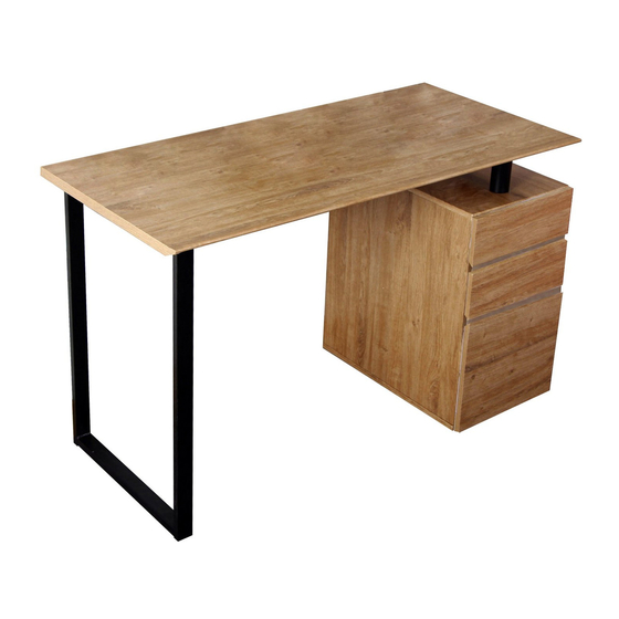
- Page 1 ASSEMBLY INSTRUCTIONS MODEL RTA-1305 Thanks for purchasing one of our products. Please read carefully the assembly instructions before the installation. Please save this manual for future reference.
-
Page 2: Main Parts List
RTA-1305 MAIN PARTS LIST NOTE: PARTS (1) AND (2) NOTE: PARTS (3) AND (4) ARE EXACTLY THE SAME ARE EXACTLY THE SAME... -
Page 3: Hardware List
RTA-1305 HARDWARE LIST Wooden Pin Small Stud Large Stud PARTS LAYOUT:... - Page 4 RTA-1305 ⚠ BEFORE YOU START THE ASSEMBLY, PLEASE READ THE FOLLOWING TIPS AND WARNINGS. ☛ Do a quick inventory to make sure the product contains all the parts and hardware. ☛ Missing, damaged and defective parts can be replaced at no cost to you. Please refer to the CONTACT and the WARRANTY cards included with the product.
- Page 5 RTA-1305 HOW TO ASSEMBLE PARTS USING CAM BOLTS AND CAM LOCKS. ☛ This is not an assembly step; it is a guide for when you are actually doing the assembly using this kind of hardware. Cam Lock Cam Bolt 1. Screw the bolt into the corresponding panel.
- Page 6 RTA-1305 Assemble the small drawer back panel (6) to the side panels (5) and (7) using screws (A) as shown. PER DRAWER Insert the drawer bottom panel (8) in between the groves of panels (5), (6) and (7) as shown.
- Page 7 RTA-1305 Assemble the drawer front panel (9) to the side panels (5) and (7) using cam bolts (B) and cam locks (C) as shown and explained in page 5. PER DRAWER Please refer to page 5. PER DRAWER REPEAT STEPS 1-3 TO ASSEMBLE THE SECOND SMALL DRAWER.
- Page 8 RTA-1305 Assemble the rails (1b) and (2b) to the side panels (5) and (7) using screws (D) as shown. ☛ Tip: Both rails are exactly the same. PER DRAWER REPEAT THIS STEP FOR THE SECOND SMALL DRAWER. First assemble the back panel (11) to the left panel (10) using screws (A) as shown.
- Page 9 RTA-1305 Insert the drawer bottom panel (8) in between the groves of panels (10), (11) and (12) as shown. ☛ Tip: The laminate might be covering the groves, and if this is the case, pierce first with the tip of a pen or screwdriver.
- Page 10 RTA-1305 P.10 P.10 Assemble the sliders (3b) and (4b) to the side panels (10) and (12) using screws (D) as shown. ☛ Tip: Both rails are exactly the same. With the panels (15) and (16) positioned as shown, assemble the sliders (1a), (2a), (3a) and (4a) to the panels using screws (D) EXACTLY as shown.
- Page 11 P.11 RTA-1305 P.11 Attach the cam bolts (C) to the panels (15) and (16), and insert the wooden pins (E) as shown. ☛ The bolts go at top, the wooden pins at bottom. Insert the cam locks (B) into back panel (17) and both panels (18) and assemble these panels in between the left panel (15) and the right panel (16) as shown and explained in page 5.
- Page 12 RTA-1305 P.12 P.12 Attach the cam bolts (C) to the cabinet top panel (19), and insert the pins (E) as shown. Assemble the cabinet top panel (19) to panels (15), (16) and (17) using cam locks (B) as shown and explained in page 5.
- Page 13 RTA-1305 P.13 P.13 First attach the studs (F) to the underside of bottom panel (20), then attach the pins (E) to the top side as shown. ☛ Make sure to install the pins into the correct holes, as the other are for screws on the next step.
- Page 14 RTA-1305 P.14 P.14 With the tabletop (21) upside-down, first assemble the structure (22) and the support tubes (23) using screws (G), then attach the studs (G) to the structure (22) as shown.
- Page 15 RTA-1305 P.15 P.15 Assemble the support tubes (23) that are attached to the tabletop (21) to the cabinet top panel (19) using screws (I). ☛ Assembly tip: First attach the back support tube and leave the screw loose, then attach the front support tube, and proceed to tighten both screws.
- Page 16 RTA-1305 P.16 P.16 ⚠ AFTER THE ASSEMBLY IS DONE, PLEASE READ THE FOLLOWING WARNINGS FOR CARE AND MAINTENANCE: ☛ Do not expose the surfaces to direct sunlight or to extreme environmental conditions. Damages caused by this kind of exposure is not covered by the product’s warranty.
Need help?
Do you have a question about the TECHNI MOBILi RTA-1305 and is the answer not in the manual?
Questions and answers