Table of Contents
Advertisement
Quick Links
RESISTRON
RES-402
Operating
Instructions
Important features
•
Microprocessor technology
•
Automatic zero calibration (AUTOCAL)
•
Automatic optimization (AUTOTUNE)
•
Automatic configuration of the secondary voltage and current ranges
(AUTORANGE, as of January 2006)
•
Automatic frequency adjustment
•
Temperature range: 300°C
•
Large current and voltage range
•
Electrically isolated analog input for set point selection with potentiometer or 0...10VDC
•
Electrically isolated 0...10VDC analog output for ACTUAL temperature
•
24VDC control signals for START, AUTOCAL and RESET with electrical isolation
•
Alarm function
Industrie-Elektronik GmbH
Gansäcker 21
D-74321-Bietigheim-Bissingen (Germany)
GB
Tel: +49/(0)7142/7776-0
Fax: +49/(0)7142/7776-19
E-Mail:
info@ropex.de
Internet:
www.ropex.de
Data subject to change
Advertisement
Table of Contents

Subscribe to Our Youtube Channel
Related Manuals for Ropex RESISTRON RES-402


Summary of Contents for Ropex RESISTRON RES-402
- Page 1 Electrically isolated 0…10VDC analog output for ACTUAL temperature • 24VDC control signals for START, AUTOCAL and RESET with electrical isolation • Alarm function Industrie-Elektronik GmbH Tel: +49/(0)7142/7776-0 E-Mail: info@ropex.de Gansäcker 21 Fax: +49/(0)7142/7776-19 Internet: www.ropex.de D-74321-Bietigheim-Bissingen (Germany) Data subject to change...
-
Page 2: Table Of Contents
Contents Safety and warning notes ....3 Startup and operation ....15 Use . -
Page 3: Safety And Warning Notes
The resistance of the heatsealing band which is used must have a positive minimum Only the original ROPEX PEX-W2 or PEX-W3 temperature coefficient in order to guarantee current transformer may be used. Other trouble-free... -
Page 4: Line Filter
DIN EN 61010-1 Safety provisions for electrical (VDE 0411-1) measuring, control and laboratory The use of an original ROPEX line filter is mandatory in devices (low voltage directive). order to comply with the standards and provisions Overvoltage category III, pollution mentioned in section 1.7 "Standards / CE marking"... -
Page 5: Principle Of Operation
Principle of operation • etc. • Increased machine capacity The use of RESISTRON temperature controllers • Extended life of the heatsealing bands and teflon coatings results in: • Simple operation and control of the sealing process • Repeatable quality of the heatseals under any conditions Principle of operation The resistance of the heatsealing band, which is... -
Page 6: Description Of The Controller
Description of the controller Description of the controller microprocessor technology endows • Increased protection against dangerous conditions, such as overheating of the heatsealing band. RESISTRON temperature controller RES-402 with previously unattainable capabilities: The electrically isolated analog interfaces for the temperature set point and the actual temperature •... -
Page 7: Modifications (Mods)
Designed according to VDE 0570/EN 61558 with a one-section bobbin. Optimized for impulse operation with RESISTRON temperature controllers. Specified according to the heatsealing application ROPEX Application Report). Communication interface CI-USB-1 Interface for connecting a RESISTRON temperature controller with diagnostic inter- face (DIAG) to the PC (USB port). -
Page 8: Technical Data
Technical data Technical data Type of construction Housing for installation in the electrical cabinet Snaps onto a standard top hat rail (DIN TS35 rail, 35mm) acc. to DIN EN 50022 Dimensions: 90 x 75mm; height: 135mm (incl. terminals) Line voltage All controllers manufactured as of January 2006: 115VAC version: 110VAC -15%…120VAC +10% (equivalent to 94…132VAC) 230VAC version: 220VAC -15%…240VAC +10% (equivalent to 187…264VAC) -
Page 9: Dimensions
Dimensions Installation If several controllers are installed on one top hat rail (DIN TS35 rail), a clearance of at least 20mm should be allowed between them. The moving clip required for fastening must be facing down for mounting on a horizontal top hat rail. End holders to mechanical fix the controller must be fitted at both ends for mounting on a vertical top hat rail. -
Page 10: Installation
8.3 "Power supply" page 12, section 8.6 "Auxiliary voltage" on page 14 and the Proceed as follows to install the RESISTRON ROPEX Application Report. information temperature controller RES-402: provided in section 8.2 "Installation steps" on 1. Switch off the line voltage and verify that all circuits page 11 must be heeded additionally. -
Page 11: Installation Steps
Installation Installation steps Use heatseal bands with suitable temperature coefficient Heatseal element push-on with coppered ends connectors Heatsealing band R= f (T) No additional Connect U measuring resistance wires directly to in secondary Note heatsealing band ends circuit number Sufficient wire of turns Twisted cross-section... -
Page 12: Power Supply
Use transformers with a one section bobbin. The power, duty cycle and voltage values must be determined individually according to the application SEC. ROPEX Application Report and "Accessories" leaflet for impulse transformers). Wiring The wire cross-sections depend on the application ROPEX Application Report). -
Page 13: Line Filter
CE mark. The wiring instructions contained in section 8.3 "Power ROPEX line filters are specially optimized for use in supply" on page 12 must be observed. RESISTRON control loops. Providing that they are... -
Page 14: Auxiliary Voltage
Installation Auxiliary voltage maximum current input of 1,0A and it is also protected against reverse polarity. Since the inputs and outputs of the RES-402 are electrically isolated, a 24VDC auxiliary voltage must be Wiring diagram applied to terminals 14+13. The auxiliary voltage has a Line filter LF-xx480 RES-402 LINE... -
Page 15: Startup And Operation
The secondary voltage and current ranges are You can find the exact configuration of the automatically configured by the automatic calibration DIP switches in the ROPEX Application function (AUTOCAL). The voltage is configured in the Report calculated for your particular application. -
Page 16: Heatsealing Band
( section 9.3.2 two turns ( ROPEX Application Report). "Burning in the heatsealing band" on page 16). One very important design feature is the copper or silver-plating of the heatsealing band ends. Cold ends... -
Page 17: Startup Procedure
December 2005, the settings of the DIP switches on incorrect ( section 9.2 "Controller configuration" the controller are indicated in the ROPEX on page 15 and ROPEX Application Report). Application Report and depend on the heatsealing Repeat the calibration after the controller has been... - Page 18 Startup and operation 9.4.2 Restart after replacing the direction. This kind of behavior would indicate that the U measuring wires have been laid incorrectly. heatsealing band If an error code is displayed, please proceed as To replace the heatsealing band, proceed as described described in section 10.9 "Error messages"...
-
Page 19: Controller Functions
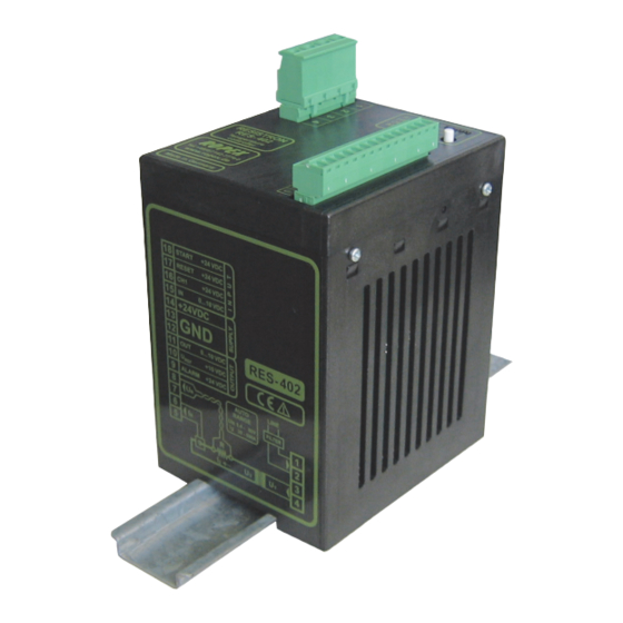
RESISTRON of AUTOCAL process. RES- 402 Temperature controller Button for manual activation of AUTOCAL ROPEX function (zero calibration). Do not press unless heatsealing band is cold. Tel:+49(0)7142-7776-0 Made in Germany Manufactured up to December 2005 Red LED, lights up or blinks to indicate ALARM. -
Page 20: Temperature Setting
The relationship between the potentiometer setting and the SET temperature is linear. The connecting wires between the controller and the potentiometer must be shielded. If a ROPEX PD-3 precision potentiometer is used, the SET temperature can be adjusted exactly with the help Page 20 RES-402... -
Page 21: Temperature Indication
An indicating instrument can be connected to this at terminals 11+12. output in order to visualize the temperature of the heatsealing band. The characteristics of the ROPEX ATR-3 temperature RES-402 meter (size, scaling, dynamic response) are ideally suited to this application and this instrument should Actual value max. - Page 22 Controller functions 20°C. The "AUTOCAL" function is activated by The yellow LED on the front panel lights up when the pressing the AUTOCAL button on the controller. "AUTOCAL" function is active. The actual value output (terminals 11+12) is 0…3°C (corresponds to app. 0 VDC).
-
Page 23: Start" Signal (Heat)
Controller functions 10.5 "START" signal (HEAT) • A heatsealing cycle is aborted if one is in progress • No more measuring impulses are generated When the "START" signal is activated, the controller- • An alarm signal is reset if one is present internal set/actual comparison is enabled and the (Note: The alarm signal is not reset until the heatsealing band is heated up to the SET temperature. -
Page 24: Diagnostic Interface/Visualization Software
An alarm can only be reset by applying a damage to the controller. "RESET" signal switching controller off and then on again. The ROPEX visualization software is described in a separate document. If an alarm signal is reset using the "RESET" signal, "RESET" signal must deactivated first. -
Page 25: Factory Settings
Factory settings Factory settings The RESISTRON temperature controller RES-402 is configured in the factory as follows: DIP switches = 6…60VAC = 30…100A secondary voltage and current I DIP switches: 2 ON (up to December 1, 3, 4, 5 OFF 2005) These switches are automatically set by the AUTORANGE function on all controllers manufactured as of January... -
Page 26: How To Order
Line filter LF- . . 480 06: Continuous current 6A, 480VAC, Art. No. 885500 35: Continuous current 35A, 480VAC, Art. No. 885506 Impulse transformer See ROPEX Application Report for design and ordering information Communiction interface CI-USB-1 Art. No. 885650 Potentiometer PD- 3 For 300°C range, Art. -
Page 27: Index
Index Index Accessories Line filter Actual value output Line frequency Alarm output Line voltage Alloy Ambient temperature Analog input Maintenance Analog output Modifications Analog temperature meter MODs Application Monitoring current transformer Application Report AUTOCAL Automatic zero calibration Overheating of heatsealing band AUTOTUNE Auxiliary voltage PEX-W2/-W3... - Page 28 Index Wiring diagram Wiring Page 28 RES-402...
Need help?
Do you have a question about the RESISTRON RES-402 and is the answer not in the manual?
Questions and answers