Sign In
Upload
Download
Table of Contents
Contents
Add to my manuals
Delete from my manuals
Share
URL of this page:
HTML Link:
Bookmark this page
Add
Manual will be automatically added to "My Manuals"
Print this page
×
Bookmark added
×
Added to my manuals
Manuals
Brands
Fellowes Manuals
Paper Shredder
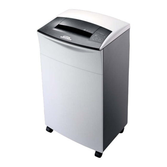
220-2
Technical & service manual
Fellowes 220-2 Technical & Service Manual
Hide thumbs
Also See for 220-2
:
Owner's manual
(5 pages)
,
User manual
(9 pages)
1
2
3
4
Table Of Contents
5
6
7
8
9
10
11
12
13
14
15
16
17
18
19
20
21
22
23
24
25
26
27
28
29
30
31
32
33
34
35
36
37
38
39
40
41
42
43
44
45
46
page
of
46
Go
/
46
Contents
Table of Contents
Troubleshooting
Bookmarks
Table of Contents
Table of Contents
Introduction
Model 220-2 and C-220
Model 220C-2 and C-220C
Safety
General Maintenance
External Cleaning
Internal Cleaning
Inspection
Lubrication
Operation
Troubleshooting
Paper Feed Problems
Electrical Problems
Mechanical Problems
Troubleshooting Flowcharts
Tools and Supplies
Cabinet and Housing
Replace Caster Assembly
Remove Housing Cover
Remove/Replace PC Board
Mechanical Assemblies
Remove Cutting Assembly and Motor from Cabinet
Remove Cutting Assembly Gears
Remove Motor
220-2 and C-220 Cutting Assembly
Repair 220-2 and C-220 Cutting Assembly
Reassemble 220-2 and C-220 Cutting Assembly
220C-2 and C-220C Cutting Assembly
Repair 220C-2 and C-220C Cutting Assembly
Reassemble 220C-2 and C-220C Cutting Assembly
Electrical Assemblies
Replace Capacitor
Replace Power Cord
Replace Basket Full Sensor
Replace Door Closed Switch
Replace Operator Panel Switches
Troubleshooting Leds
Replace Paper Feed Sensor
Current Limit Adjustment
Wiring Diagrams
Models 220-2, 220C-2, C-220, and C-220C
Parts Lists
Cabinet and Housing
Motor
Cabinet
Cutting Assembly
Gear Box and Gears
Electrical Components
Miscellaneous
Advertisement
Quick Links
1
Models 220-2, 220C-2, C-220, and C-220C
2
Cabinet
3
Cutting Assembly
4
Gear Box and Gears
5
Electrical Components
6
Miscellaneous
Download this manual
Technical Service Manual
For all models up to and
including:
38221 Rev D
32221 Rev B
38221-71 Rev C
38221-72 Rev C
38221-73 Rev C
38222-71 Rev B
38222-72 Rev C
38222-73 Rev B
32222 Rev C
38225-71 Rev D
38225-72 Rev D
38225-73 Rev D
38225 Rev E
June 2007
for Models
220-2
220C-2
C-220
C-220C
Table of
Contents
Previous
Page
Next
Page
1
2
3
4
5
Advertisement
Table of Contents
Troubleshooting
Troubleshooting
11
Mechanical Problems
13
Replace Operator Panel Switches
35
Need help?
Do you have a question about the 220-2 and is the answer not in the manual?
Ask a question
Questions and answers
Related Manuals for Fellowes 220-2
Paper Shredder Fellowes 220-2 User Manual
(9 pages)
Paper Shredder Fellowes 220-2 Owner's Manual
Fellowes commercial shredder owner's manual (5 pages)
Paper Shredder Fellowes Microshred MS-460Cs Brochure & Specs
Fellowes shredder brochure (24 pages)
Paper Shredder Fellowes C-220 Instructions Manual
(6 pages)
Paper Shredder Fellowes C220 Instruction Manual
(3 pages)
Paper Shredder Fellowes Powershred C-220 User Manual
Fellowes paper shredder - shredder user manual (2 pages)
Paper Shredder Fellowes Powershred C-220 Instructions
(2 pages)
Paper Shredder Fellowes 190 Operating Instructions Manual
Fellowes powershred operating instructions 190, 200, 220, 220cc (8 pages)
Paper Shredder Fellowes Powershred 280 Operating Instructions Manual
Console shredders (11 pages)
Paper Shredder Fellowes FORTISHRED 2250C Instructions
(4 pages)
Paper Shredder Fellowes Fortishred 2250C Manual
(41 pages)
Paper Shredder Fellowes POWERSHRED 225Mi User Manual
(15 pages)
Paper Shredder Fellowes Powershred Series Technical & Service Manual
(32 pages)
Paper Shredder Fellowes POWERSHRED 225Mi Quick Start Manual
(6 pages)
Paper Shredder Fellowes 225Ci Instruction Manual
Powershred (14 pages)
Paper Shredder Fellowes Powershred 225i Manual
(80 pages)
This manual is also suitable for:
220c-2
C-220
C-220c
Table of Contents
Save PDF
Print
Rename the bookmark
Delete bookmark?
Delete from my manuals?
Login
Sign In
OR
Sign in with Facebook
Sign in with Google
Upload manual
Upload from disk
Upload from URL


Need help?
Do you have a question about the 220-2 and is the answer not in the manual?
Questions and answers