Table of Contents
Advertisement
Advertisement
Table of Contents

Subscribe to Our Youtube Channel
Related Manuals for Dahua VTH1510A


Summary of Contents for Dahua VTH1510A
- Page 1 VTH15 Series User’s Manual V1.1...
-
Page 2: Table Of Contents
Table of Contents General Introduction ..................4 1.1 Model List ......................4 1.2 Front Panel ......................5 1.3 Rear Panel ......................10 Installation ....................13 2.1 Install Device ....................13 2.1.1 Embedded Box ................... 13 2.1.2 Direct Installation ..................15 2.2 Wiring ....................... - Page 3 Important Safeguards and Warnings Please read the following safeguards and warnings carefully before using the product in order to avoid damages and losses. Note: Do not expose the device to lampblack, steam or dust. Otherwise it may cause fire or ...
-
Page 4: General Introduction
1.1 Model List This manual is for the following product models; please carefully check your model and corresponding functions. VTH15 Series Model Front Camera Screen SD Card VTH1510A Not support Resistive Not support touch screen VTH1520A Not support Resistive Support... -
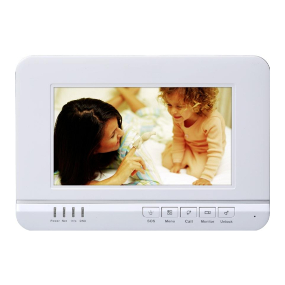
Page 5: Front Panel
1.2 Front Panel Figure 1- 1 VTH15 Series A Model Figure 1- 2 VTH15 Series AH Model... - Page 6 Figure 1- 3 VTH15 Series AS Model...
- Page 7 Figure 1- 4 VTH15 Series AS-H Model...
- Page 8 Figure 1- 5 VTH15 Series B(W) Model Figure 1- 6 VTH15 Series CH Model...
- Page 9 Figure 1- 7 VTH15 Series CS Model Different models of VTH may have slightly different button locations, but same silk-screens still correspond to the same function. See Figure 1- 8 and Figure 1- 9. Figure 1- 8...
-
Page 10: Rear Panel
Figure 1- 9 Name Note Emergent call to center. Arm/Menu Press this button to return to main menu or arm. Under calling, status, press this button to answer call. During Call a call, press this button to hang up. Monitor Monitor VTO video. - Page 11 Figure 1- 10 VTH15 Series AH Model Name Note 8-ch alarm, may connect to external alarm extension Alarm port module, refer to label for details. Debug port For installation staff use only. Network port Plug in network cable. Handset port For model with handset only.
- Page 12 Figure 1- 11 VTH15 Series CH Model Name Description Alarm Port 8-ch alarm, please refer to tag. Debug Port Extension port, for RS485 communication port. Network Port Plug in network cable. Note: Alarm Output Reserved port. Power Port Connect to 2-pin green 12V power supply.
-
Page 13: Installation
2 Installation 2.1 Install Device It introduces two installation methods as embedded box and direct installation. Warning: Avoid the indoor unit installed in adverse environments, such as condensation and high temperature environment, oil and dust environment, chemically aggressive environments, direct sunlight environment. - Page 14 Figure 2- 1 2.1.1.2 Metal Case This installation method is for CH model only, including VTH1510CH and VTH1520CH. Screw Component Name Illustration Quantity M4×30 cross pan head machine screw Installation Step Step 1. Embed metal case into wall. Step 2.
-
Page 15: Direct Installation
Figure 2- 2 2.1.2 Direct Installation Direct installation is not to dig holes on wall, instead all wiring go from the side. Installation Step Step 1. Fix installation bracket on wall, with screw (M4×30 cross pan head machine screw). Step 2. Fix the device unit on installation bracket with buckle. Figure 2- 3 2.2 Wiring Please refer to Ch 1.3. -
Page 16: Product Function
3 Product Function Digital VTH can unlock, alarm, talk, monitor, search message and set some system performances. 3.1 Main Menu The product main interface has four menus: Video Talk, Security, Message, and Settings. See Figure 3- 1 VTH15 series. Figure 3- 1 VTH15 series Icon Name Note... - Page 17 Figure 3- 2 Set Password Step 1. Click Password, and you can set password for user, unlock, arm/disarm and anti-hijack. Figure 3- 3 User password initial value is 123456 Unlock password initial value is null Arm password initial value is 123456 ...
- Page 18 Figure 3- 4 Ring Settings Click Ring Settings, you can set phone ring, alarm ring, click increase/decrease volume. Figure 3- 5 Talk Settings Step 1. Click Talk settings, you can set VTO and VTH’s ring time, call time, monitor time, record time and message time.
- Page 19 Figure 3- 6 Step 1. Click to increase time, click to reduce time. Unit is second. Step 2. Click OK. DND Settings Click DND Settings, you can set DND time (oh, 1h, 2h, 4h, 8h, 24h). Local IPC Step 1.
- Page 20 Step 3. In homepage, click , you can view added IPC video window. Clean Click Clean, the screen will be locked for 10s and you can clean the screen during this time period. Default Click Default to restore default settings. ...
- Page 21 Figure 3- 9 Network You can go to Project Settings>Network interface, set master VTO name, master VTO IP. Figure 3- 10 IPC Info If IPC is connected, you can go to Project Settings>IPC Info to view added IPC.
- Page 22 Figure 3- 11 Search Device You can search device in Search Device interface, and you also can refresh, add, modify IP and delete IP. Figure 3- 12 Default Click Default, you can restore all default project settings. 3.1.1.3 Time You can set time in Time interface.
- Page 23 Figure 3- 13 3.1.1.4 Introduction You can click Introduction to view the product’s introduction, functions and FAQ. Figure 3- 14 3.1.1.5 Info Initialization 3.1.1.6 You can initialize all information in System Info Initialization You can initialize all information in Settings tab.
-
Page 24: Video Talk
Figure 3- 15 3.1.2 Video Talk In homepage, click to enter Video Talk interface. 3.1.2.1 Call Resident Step 1. Enter room no. of resident you want to call. Step 2. Press icon to call. Once the resident picks up, you can have a bidirectional talk. Figure 3- 16... - Page 25 Click Contacts , you can call, add, edit and delete contacts. Figure 3- 17 Note: If both parties of a call are using VTH15 series CH model (with camera)m they can perorm a video talk. 3.1.2.2 Monitor Click and select unit VTO, fence station or IPC. It can call VTO(door station).
-
Page 26: Security Alarm
3.1.2.3 Record Click , you can view missed call, accepted call and called call. Figure 3- 19 3.1.2.4 Management Center Click or press SOS button, and it is to call MGT center. 3.1.3 Security Alarm In homepage, click Security Alarm to enter Security Alarm interface. 3.1.3.1 Area Status Step 1. - Page 27 Figure 3- 20 Step 2. Click Setting, input password, to enter setting interface. Note: The entry password is user password. Default password is 123456, please see Ch 3.1.2.1. Figure 3- 21 You can set bypass and delete for 4~8 channels to disable area for one time or long-term. 3.1.3.2 Recodes You can view zone alarm status in alarm record interface.
-
Page 28: Info Search
Figure 3- 22 3.1.3.3 Mode Settings Click , set area alarm mode, including Out mode, In mode, Sleep mode and Custom mode. Figure 3- 23 Note: Password to enter mode setup page is the user password, and default password is 123456. Refer to Ch 3.1.2.1. -
Page 29: Monitor
Click , you can view, delete and clear information published. Figure 3- 24 3.2 Monitor Press , you can monitor unit VTO info, or switch to fence station or IPC for monitoring. Figure 3- 25 3.3 Unlock When VTH is being called, monitored, in call status, press unlock button or unlock icon on VTH to remotely unlock door. -
Page 30: Screen Calibration
3.4 Screen Calibration The product is calibrated before shipped out from factory, and if you want to calibrate the screen, press unlock+arm/menu button to enter calibration interface. Calibrate the screen according to the tips. -
Page 31: Quick Configuration
4 Quick Configuration After configuration is complete, you have completed the connection between VTO and VTH, and you may start video talk. 4.1 Process Step 1. In device homepage, select Settings>Project Settings. Step 2. Enter project password (default password is 002236). See Figure 4- 1. - Page 32 If the VTH is extension, then select extension, and fill in room no. In Master IP, fill in master VTH’s IP address, and extensions will be automatically sync with user config of the master VTH. See Figure 4- 3. Click OK to save. Figure 4- 3 Step 4.
-
Page 33: Result Verification
Figure 4- 5 Step 7. Click OK to save. 4.2 Result Verification VTO starts to call VTH room no. VTH pops up monitoring video and buttons, see Figure 4- 6. You can accept, hand up and unlock on VTH. Note: VTH1520A\VTH1520AH\VTH1520AS\VTH1520AS-H\VTH1520CH\VTH1560B\VTH1560CS\ VTH1580CS models of VTH support record and snapshot. -
Page 34: Appendix 1 Technical Specification
Appendix 1 Technical Specification VTH15 Model Series Model A Model AH Model B(W) Model CS Model CH AS/AS-H Model System Main Built-in microcontroller Processor Operating Built-in LINUX system System Video Video Compression H.264 Standard Video 800x480 Resolution Front Only VTH1520CH supports front camera, 0.3 megapixels. Camera Audio Input... - Page 35 -10℃~+60℃ Working Environment 10~90%RH Dimensions 221mm*154 221mm*154 192mm*261 221mm*154 181mm*262 200mm*136 (L*W*H) mm*25mm mm*25mm mm*24mm mm*25mm mm*16mm mm*22 mm Weight 0.8 kg Note: This manual is for reference only. Slight difference may be found in user interface. All the designs and software here are subject to change without prior written notice.
Need help?
Do you have a question about the VTH1510A and is the answer not in the manual?
Questions and answers