Table of Contents
Advertisement
Quick Links
Advertisement
Table of Contents

Related Manuals for Dahua VTS5A40B


Summary of Contents for Dahua VTS5A40B
- Page 1 Digital VTS User's Manual V1.0.2...
-
Page 2: Foreword
Foreword This manual introduces the configurations on local VTS and webpage. Read carefully before using the VTS, and keep the manual safe for future reference. Safety Instructions The following signal words might appear in the manual. Signal Words Meaning Indicates a high potential hazard which, if not avoided, will result in death or serious injury. - Page 3 visit our official website. The manual is for reference only. Slight differences might be found between the electronic version and the paper version. All designs and software are subject to change without prior written notice. Product updates ● might result in some differences appearing between the actual product and the manual. Please contact customer service for the latest program and supplementary documentation.
-
Page 4: Important Safeguard And Warnings
Important Safeguard and Warnings This section introduces content covering the proper handling of the device, hazard prevention, and prevention of property damage. Read carefully before using the device, and comply with the guidelines when using it. Installation Requirements Do not connect the power adapter to the device while the adapter is powered on. ●... - Page 5 Do not leave the batteries in environments with extremely high temperatures to avoid ● explosions and leakage of flammable liquid or gas. Do not subject the batteries to extremely low air pressure to avoid explosions and the leakage of ● flammable liquid or gas.
-
Page 6: Table Of Contents
Table of Contents Foreword................................I Important Safeguard and Warnings........................ III 1 Device Structure.............................. 1 1.1 Front Panel............................. 1 1.2 Rear Panel...............................3 2 Initializing VTS..............................5 2.1 Initialization through Local Device...................... 5 2.2 Initialization through Webpage......................5 3 Building Scenes..............................7 3.1 Operations on Local Device........................7 3.1.1 Local Screen.......................... - Page 7 4.2.2 Configuring SIP Server......................62 4.2.3 Configuring FTP.........................63 4.2.4 Device Setting..........................64 Appendix 1 Cybersecurity Recommendations..................... 69...
-
Page 8: Device Structure
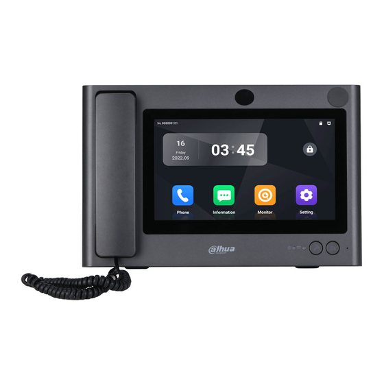
1 Device Structure 1.1 Front Panel Figure 1-1 Front panel Table 1-1 Front panel description Name Description If you lift MIC, audio and pickup are both converted into MIC. Speaker Outputs sound. RJ-11 Port Connects VTS and MIC using the telephone cord. - Page 9 Name Description From left to right: Power indicator ● On: The device is powered on. Off: The device is not connected to the power supply. Information indicator ● On: There is a missed call. Off: The missed call has been processed or there is no missed call.
-
Page 10: Rear Panel
1.2 Rear Panel Figure 1-2 Rear panel Table 1-2 Rear panel description Name Description Open the rear panel and the ports from top to bottom are: HDMI video transmission port, for video transmission ● only. Port USB port. ● USB port. ●... - Page 11 Name Description Ports from left to right are: Power output port. ● GND. ● Alarm input port 1. ● Alarm input port 2. ● Alarm input port 3. ● 12-pin Port Alarm input port 4. ● Power input port. ● GND.
-
Page 12: Initializing Vts
2 Initializing VTS You can initialize VTS through the local device or through the webpage. 2.1 Initialization through Local Device Procedure Step 1 Power on the VTS. Step 2 Select the language. Step 3 Enter the password and e-mail address. Select I have read and agree to all the terms Privacy, Software License Agreement , Step 4 and then tap Next. - Page 13 Enter the username and password, and then click Login. Step 5 Select the scene, and then click OK. Step 6 Figure 2-2 Select scene...
-
Page 14: Building Scenes
3 Building Scenes 3.1 Operations on Local Device 3.1.1 Local Screen Figure 3-1 Local screen Table 3-1 Home screen introduction Description The number of VTS. Date and time. Function buttons. Phone: Call VTH and check the call history. For details, see "3.1.8.1 Call". ●... -
Page 15: Configuring The Display Parameters
Description The connection status of the network, the SIP server, and the SD card. 3.1.2 Configuring the Display Parameters Configure the brightness and screen turn-off time. Turn on or turn off Lock Screen. Procedure On the home screen, select Setting > Step 1 Step 2 Configure the parameters. -
Page 16: Configuring The Intercom Parameters
Figure 3-3 Sound settings 3.1.4 Configuring the Intercom Parameters Configure the ringtone and call limit of VTO and VTH, and the monitoring time. Procedure Step 1 On the home screen, select Setting > Step 2 Configure the parameters. Figure 3-4 Intercom settings... -
Page 17: Configuring The Advanced Parameters
Table 3-2 Description of intercom parameters Parameter Description VTO Ringtone (s) The call from VTO stops ringing after the time you set. VTO automatically hangs up the call to VTS after the time VTO Call Limit (min) you set. VTH Ringtone (s) The call from VTH stops ringing after the time you set. -
Page 18: Resetting Password
Table 3-3 Advanced settings description Parameter Description Check the used capacity and the total capacity of the SD card if there is a SD card in VTS. SD Card Status System of numeration differs in Android system and Windows system when converting the capacity. -
Page 19: Project Settings
Figure 3-6 Reset password Get the Security Code according to the instructions, and then enter the new password Step 3 and security code. Step 4 Tap OK. 3.1.7 Project Settings 3.1.7.1 Configuring VTS Configure the number and network parameters of VTS. Procedure Step 1 Select Settings >... - Page 20 Figure 3-7 Configure the parameters Table 3-4 Parameters description Parameter Description User-defined. You can configure the number from 101 to 999. Configure the mode to get the IP. Static: Manually set Local IP , Subnet Mask and Default Gateway. ● Ethernet IP Mode DHCP (Dynamic Host Configuration Protocol): Select DHCP if there is ●...
- Page 21 Parameter Description Building No. If the platform is used as the SIP server, make sure that the ● configuration status of building and unit number is the same on the platform, VTS and VTO. If the VTO is used as the SIP server, make sure that the enable/disable ●...
- Page 22 Parameter Description Network port number of SIP server. Network Port VTO as the SIP server: 5060. ● The platform as the SIP server: 5080. ● Username Default. Password Default. Domain Name Keep consistent with the SIP server. Domain name is VDP by default. Step 4 Tap Save.
- Page 23 Add devices in batches. ● Figure 3-10 Add devices in batches Table 3-6 Parameters description Device Type Parameter Description Supports adding devices one by one or in batches. Add Mode Only VTO supports adding devices in batches. User-defined. You can configure the name that Name distinguishes the device.
- Page 24 Device Type Parameter Description Select main stream or sub stream. Main stream: Large stream has high definition, and ● occupies a large bandwidth. Used for local storage. Stream Type Sub stream: Smooth image occupies a small ● bandwidth. Used for low-bandwidth network transmission.
-
Page 25: Commissioning
Click OK. Step 6 3.1.7.5 Debugging and Factory Defaults Procedure Step 1 On the home screen, select Setting > > Project Settings. Enter the password, and then tap OK. Step 2 Step 3 , and then configure the functions. Figure 3-12 Debug and factory defaults Table 3-7 Parameters description Parameter Description... - Page 26 3.1.8.1 Call Call VTH On the home screen of VTS, tap Phone, enter the number of VTH, and then tap If you use the gooseneck to talk, the recommended distance is between 5 cm to 10 cm. Figure 3-13 Dial Figure 3-14 Call VTH...
- Page 27 Table 3-8 Icons description Icon Description Adjust the volume of the speaker during the call. Turn on or turn off speech input during the call. Tap it to convert to IPC video image during the call. Tap it to hang up the call. Call history On the home screen of VTS, tap Phone, and then tap to check all calls and missed calls.
- Page 28 Figure 3-16 Video files Snapshot files Check or delete the snapshot files that VTS recorded in monitoring or in the call. Figure 3-17 Snapshot files...
- Page 29 3.1.8.3 Monitoring Monitor VTO, fence station or IPC on VTS. The operations of monitoring IPC or fence stations are the same with the operations of monitoring VTO. This section uses monitoring VTO as an example. Prerequisites Make sure that you have added VTO, fence station or IPC before you monitor them. For details, see "3.1.7.3 Adding Devices".
-
Page 30: Operations On Webpage
Figure 3-19 Monitoring image Table 3-9 Monitoring image description Icon Description Tap to view the monitoring image in 4 windows. Tap to convert to monitor other VTOs if VTS connects more than one VTO. Remotely unlock VTO. Call VTO and VTO directly receive the call without taping any icon. Tap to start manual recording. -
Page 31: Resetting Password
Step 2 Enter the username and password. Figure 3-20 Log in to the webpage The default username of administrator is admin. The default password is the password ● that you configured during initialization. We recommend you change the password on a regular basis. -
Page 32: Home
Figure 3-21 Get the security code Enter the security code you received in the Security code text box. Step 4 Click Next. Step 5 Step 6 Reset new password and confirm the new password. The password must consist of 8 to 32 non-blank characters and contain at least two types of characters among number, letter and common character (excluding space, ', ", ;, :, &). -
Page 33: Configuring Network
Table 3-10 Home page description Parameter Description Go to the home page. Click the icon. Select Restart to restart VTS. ● Navigation Click the icon. Select Logout to log out the ● account. Open the window in a full screen mode. Function Menu Functions configuration menu of VTS. - Page 34 Figure 3-23 Configure the parameters Table 3-11 Parameters description Parameter Description Static: Manually configure IP , Subnet Mask and Default Gateway. ● Click Apply and the webpage automatically goes to the login page of the IP that you configured. Mode DHCP (Dynamic Host Configuration Protocol): Select DHCP if there is ●...
- Page 35 Click Apply. Step 4 3.2.4.2 Configuring SIP Server Configure the parameters of SIP server. Connect to VTO through SIP agreement to achieve video intercom. Procedure Step 1 Log in to the webpage of VTS. Select Network Settings > SIP Server. Step 2 Step 3 Configure the parameters.
- Page 36 3.2.4.3 Configuring Basic Services Turn on the protocol as needed when connected VTS with the third-party platform. Log in to the webpage of VTS, and then select Network Settings > Basic Services. Figure 3-25 Basic services Table 3-13 Description of basic services Service Description Common Gateway Interface (CGI) offers a standard protocol for web...
-
Page 37: System Management
3.2.4.4 Configuring Auto Registration VTS automatically register on the server, and report its IP address to designated server Procedure Step 1 Log in to the webpage of VTS. Step 2 Select Network Settings > Auto Registration. Turn on Enable. Enter the server address, port number and sub-device ID. Step 3 Figure 3-26 Auto registration Table 3-14 Parameters description... - Page 38 Figure 3-27 Configure basic parameters Click Apply. Step 4 3.2.5.2 Configuring Video Parameters Background Information Video is available on select models. Procedure Step 1 Log in to the webpage of VTS. Select System > Video. Step 2 Step 3 Configure the parameters. Figure 3-28 Video parameters...
- Page 39 Table 3-15 Parameters description Parameter Description PAL: The default stream frame rate is 25 fps. ● Video Standard NTSC: The default stream frame rate is 30 fps. ● Select the compression mode depending on the actual bandwidth. Compression H.264: Main profile compression. ●...
- Page 40 Figure 3-29 Add users Table 3-16 Description of user parameters Parameter Description User’s unique identification. You cannot use existing user name. The Username max. length of the username is 31 characters which consist of number, letter, underline, dash, dot and @. Password The password must consist of 8–32 non-blank characters and contain at least two types of number, letter, and special characters (excluding ' "...
- Page 41 3.2.5.3.2 Resetting Password Reset password through the e-mail address that you bound if you forget the password. Procedure Step 1 Log in to the webpage of VTS. Select System > Account. Step 2 Step 3 Click to enable Password Reset. Step 4 Enter the email address and configure the password expiry period.
- Page 42 Figure 3-31 Add ONVIF user Table 3-17 Description of ONVIF user parameters parameter Description User’s unique identification. You cannot use existed username. The max Username length of the user or group name is 31 characters which consist of number, letter, underline, dash, dot and @. Password The password must consist of 8–32 non-blank characters and contain at least two types of number, letter, and special characters (excluding ' "...
- Page 43 3.2.5.4 Viewing Online User Log in to the webpage of VTS. Select System > Online User to view the current users logging into the web. You can view username, IP address and login time. Figure 3-32 Online user 3.2.5.5 Configuring Time You can configure date, time zone, and NTP (Network Time Protocol) server.
- Page 44 Parameter Description If you select Manual Settings, configure the system time manually. Time Click Sync PC, and the system time changes to the PC time. Server If you select NTP, the system then syncs time with the internet server in real time. Port You can also enter the IP address, port, and interval of a Interval...
- Page 45 Figure 3-35 Configuration management 3.2.5.7.1 Import/Export Configuration File Import or export the system configuration file. Use configuration backup file when many devices need the same parameters configuration. Export configuration file Click Export Configuration File to export the system configuration file to local storage. The export file excludes IP information.
-
Page 46: Device Management
3.2.5.8 Updating Background Information Do not power off the device or the network, restart or turn off the device. ● If wrong upgrade file has been used, restart the device; otherwise some functions might not ● work properly. Degrade has potential security risks. Operate it carefully. ●... - Page 47 Select Device Setting > IPC Info. Step 2 Step 3 Click to configure the parameters of IPC. Figure 3-36 Configure IPC Table 3-19 Description of IPC parameters Parameter Description Name User-defined. You can configure the name that distinguishes the device. IP Address IP address of the added IPC.
-
Page 48: Log
Parameter Description Username The username and password of the IPC that you added. Password 3.2.6.2 Adding VTO or Fence Station Procedure Step 1 Log in to the webpage of VTS. Select Device Setting > Device Setting > All. Step 2 Click Add. -
Page 49: Security
3.2.7.1 Viewing System Log Procedure Step 1 Log in to the webpage of VTS. Select Log > Log. Step 2 Step 3 Select the log type, configure the time range, and then click Click Export to export the log to the local computer. If you select Encrypt Log ●... - Page 50 Figure 3-39 Security status User & Service Detection If the configuration of the detection item conforms to the recommendation, the icon is green. ● If the detection item needs to be optimized, the icon is yellow. Click Details to view the details ●...
- Page 51 If there is no certificate in the list, click Certificate Management at the left navigation bar. For details, see "3.2.8.4 Installing Device Certificate". Figure 3-40 HTTPS Click Apply. Step 5 Results Enter https://IPaddress: https port in the browser. If you have already installed the certificate, the normal login page will be displayed. ●...
- Page 52 Figure 3-42 Add the address Click Apply. Step 6 Related Operations Click to edit the host information. ● Click to delete the host information. ● 3.2.8.3.2 Configuring Account Lockout If you consecutively enter a wrong password more than the configured value, the account will be locked.
- Page 53 Lock time: The period during which you cannot log in after the login attempts reaches ● upper limit. Figure 3-43 Account lockout Click Apply. Step 4 3.2.8.3.3 Configuring Anti-DoS Attack You can enable SYN Flood Attack Defense and ICMP Flood Attack Defense to defend the device against DoS (Denial of Service) attack.
- Page 54 Figure 3-44 Anti-DoS Attack Click Apply. Step 4 3.2.8.4 Installing Device Certificate Create a certificate or upload an authenticated certificate, for example when you log in through HTTPS with your PC, you need to verify device certificate. 3.2.8.4.1 Creating Certificate Procedure Step 1 Log in to the webpage of VTS.
- Page 55 Figure 3-45 Certificate Information (1) Click Create and install certificate. Step 6 After the certificate is created successfully, you can view the created certificate on the Device Certificate page. Related Operations Click Enter Edit Mode to edit the custom name of the certificate. ●...
- Page 56 Figure 3-46 Certificate information (2) Step 6 Click Create and Download. Save the request file to your PC. Step 7 Apply for the CA certificate from the third-party certificate authority. Step 8 Import the signed CA certificate. 1. Save the CA certificate to the PC. 2.
- Page 57 After the certificate is created successfully, you can view the created certificate on the Device Certificate page. Click Recreate to create the request file again. ● Click Import Later to import the certificate next time. ● Related Operations Click Enter Edit Mode to edit the custom name of the certificate. ●...
- Page 58 Click to delete the certificate. ● 3.2.8.5 Installing Trusted CA Certificate CA certificate is a digital certificate for the legal identity of the camera. For example, when the camera accesses the LAN through 802.1x, the CA certificate is required. Procedure Step 1 Log in to the webpage of VTS.
- Page 59 Figure 3-50 Video encryption Table 3-20 Description of video encryption parameters Area Parameter Description Enable Enable stream frame encryption by using private protocol. Encryption Type Click to enable audio and video encryption during data transmission. Select the encryption type, and then Private Protocol configure update period of secret key.
-
Page 60: Industrial Scenes
4 Industrial Scenes 4.1 Operations on Local Device This chapter introduces different configurations in industrial scene. Other configurations are the same with that in buildings scene. 4.1.1 Local Screen Figure 4-1 Local screen Table 4-1 Home screen introduction Description The number of VTS. Date and time. -
Page 61: Configuring Intercom Parameters
Description to lock the screen. If you select Setting > Display Settings, and turn on Lock Screen , you need to enter the default password 123456 to unlock the screen when you lock it after the configuration. The connection status of the network, the SIP server, and the SD card. 4.1.2 Configuring Intercom Parameters On the home screen, select Setting >... -
Page 62: Project Settings
4.1.4 Project Settings 4.1.4.1 Configuring VTS Configure the number and network parameters of VTS. Procedure Select Settings > > Project Setting on the home screen. Step 1 Enter the password, and then tap OK. Step 2 Step 3 , and then configure the parameters. Figure 4-3 Configure the parameters Table 4-2 Description of VTS parameters Parameter... -
Page 63: Commissioning
Parameter Description Default Gateway DNS 1 IP address of DNS server. DNS 2 Standby IP address of DNS server. Turn on password protection. The password is transferred in encryption Password Protection when the device is registered on the platform through SIP. 4.1.4.2 Configuring Protocols Procedure Select Settings >... - Page 64 Figure 4-4 Select the terminal devices Step 3 Select Broadcast Type , and then tap Start Broadcast. Audio File: Select the audio in the audio file list, and then tap Start Broadcast to play ● the audio. Manual Broadcast: Tap Start Broadcast, and then tap to broadcast.
- Page 65 Figure 4-6 Manual broadcasting 4.1.5.1.2 Broadcasting on All Devices Procedure Step 1 Tap Broadcast on the home screen of VTS. Tap Select All Devices. Step 2 Step 3 Select Broadcast Type, and then start broadcast. Audio File: Select the audio in the audio file list, and then tap Start Broadcast to play ●...
- Page 66 Figure 4-7 Call history Video Figure 4-8 Video files...
- Page 67 Snapshot Figure 4-9 Snapshot files 4.1.5.3 Monitoring VTS as the lower-level VTS: You can monitor and call VTA. IPC and VTA receive the call. ● VTS as the upper-level VTS: You can monitor and call VTA. ● Use monitoring VTA as an example. Tap Monitor on the home screen of VTS, and then tap the icon of VTA.
-
Page 68: Operations On Webpage
Figure 4-10 Monitor VTA Table 4-4 Monitoring image description Icon Description Tap to view the monitoring image in 4 windows. Tap to convert to monitoring image of other terminal devices if VTS connects more than one terminal devices. Tap to receive the audio from VTA. Talk with the peer device. -
Page 69: Configuring Device Role
4.2.1 Configuring Device Role Procedure Step 1 Log in to the webpage of the device. Select System > General. Step 2 Step 3 Configure the parameters. Figure 4-11 Configure the parameters Table 4-5 Description of the device role parameters Parameter Description Select from lower-level VTS, upper-level VTS and platform client. -
Page 70: Configuring Ftp
Figure 4-12 SIP server parameters Table 4-6 Parameters description Parameter Description IP Address IP address of SIP server. Network port number of SIP server. Port The platform as the SIP server: 5080. Username Default. Password Default. SIP Domain Keep consistent with the SIP server. Domain name is VDP by default. Tap Save. -
Page 71: Device Setting
4.2.4 Device Setting 4.2.4.1 Using with the Platform When using the device with the platform, enable the SIP server, and then configure the parameters. 4.2.4.1.1 Call Forwarding Log in to the webpage of VTS, and then select Device Setting > Call Forwarding. Enable Always Forward , and then click Apply. - Page 72 1. Click Add. 2. Configure the parameters, and then click OK. 4.2.4.2 Using without the Platform When using the device without the platform, configure the device role as lower-level VTS or upper- level VTS. 4.2.4.2.1 Call Forwarding Manage the forwarding and receiving of the call between the VTS devices. When the call of device A is forwarded to device B, configure Forwarding on device A, and then configure Receiving on device B.
- Page 73 Parameter Description Regular call: Intercom between VTS and other VTS. ● Entrusting: All calls of the current VTS will be forwarded to other VTS. ● Service Call Forwarding: If the current VTS missed the call, the call will be ● forwarded to other VTS.
- Page 74 Figure 4-16 Add VTA Table 4-8 Parameters description Parameter Description Select Monitor > Terminal Management on the VTS, and then you can Group view the devices of the group that you configured. Device Name User-defined. Device Model Enter the complete device model that you can get from the device label. You can add VTA in the following 2 ways.
- Page 75 4.2.4.2.3 Adding Lower-level VTS When the device is configured as upper-level VTS, you can add the lower-level VTS. Procedure Step 1 Log in to the webpage of the device. Select Device Setting > Terminal Management. Step 2 Click Add. Step 3 Step 4 Enter IP address, username and password of the VTS.
-
Page 76: Appendix 1 Cybersecurity Recommendations
Appendix 1 Cybersecurity Recommendations Mandatory actions to be taken for basic device network security: 1. Use Strong Passwords Please refer to the following suggestions to set passwords: The length should not be less than 8 characters. ● Include at least two types of characters; character types include upper and lower case letters, ●... - Page 77 According to business and management requirements, reasonably add users and assign a minimum set of permissions to them. 9. Disable Unnecessary Services and Choose Secure Modes If not needed, it is recommended to turn off some services such as SNMP, SMTP, UPnP, etc., to reduce risks.
Need help?
Do you have a question about the VTS5A40B and is the answer not in the manual?
Questions and answers