Table of Contents
Advertisement
Quick Links
Advertisement
Table of Contents

Related Manuals for MiTAC 6515WU


Summary of Contents for MiTAC 6515WU
- Page 1 6515WU Motherboard Reference Part Number : 5615 7030 0001 R00 (Jul. 2000)
- Page 2 Trademarks All brand and product names are trademarks or registered trademarks of their respective companies. Note The information in this guide is subject to change without notice.
- Page 3 Caution Texts Concerning Lithium Batteries DANISH ADVARSEL! Lithiumbatteri - Eksplosionsfare ved fejlagtig håndtering. Udskiftning må kun ske med batteri af samme fabrikat og type. Levér det brugte batteri tilbage til leverandøren. NORWEGIAN ADVARSEL: Eksplosjonsfare ved feilaktig skifte av batteri. Benytt samme batteritype eller en tilsvarende type anbefalt av apparatfabrikanten.
- Page 4 Class B Regulations U. S. A. Federal Communications Commission Radio Frequency Interference Statement This equipment has been tested and found to comply with the limits for a Class B digital device pursuant to Part 15 of the FCC Rules. These limits are designed to provide reasonable protection against harmful interference in a residential installation.
- Page 5 Important Safety Instructions Read all of these instructions. • Follow all warnings and instructions marked on the product. • Unplug this product from the wall outlet before installing an add-on card inside • this product. Do not use this product near water. •...
-
Page 6: Table Of Contents
Table of Contents Preface ...................... 8 Chapter 1 Introduction................. 9 Features ..................9 Specifications .................9 CPU, Memory, and Main Components ........9 Interfaces and Controllers............10 Chapter 2 System Components ............11 Major Components...............11 Block Diagram................14 Chapter 3 Connector and Jumper Definition........15 Connector Definitions..............16 Internal Connectors..............16 External Connectors ...............16... - Page 7 List of Figures Figure 2-1. Major Components of System Board ......11 Figure 2-2. Block Diagram of System Board ....... 14 Figure 3-1. Connector and Jumper Locations ......15 Figure 4-1. Inserting CPU ............18 Figure 4-2. Installing CPU............19 Figure 4-3.
-
Page 8: Preface
Preface This manual contains basic information necessary for both the end user and service personnel. Although most of the information you need are contained in this manual, we recommend you to contact an authorized dealer for service purposes. Making personal alterations to the system can violate the effectivity of your warranty. -
Page 9: Chapter 1 Introduction
Chapter 1 Introduction This chapter introduces the specifications and the features of the motherboard. Features 66/100/133 FSB Socket 370 CPU Support • AGP Interface • The AGP (Accelerated Graphics Port) interface is integrated into the system. Plug and Play support •... -
Page 10: Interfaces And Controllers
System Memory • Two 168-pin DIMM sockets to support 8/16/32/64/128/256/512MB SDRAM memory modules, configurable up to 512MB ROM BIOS • 4Mb flash EEPROM, supporting audio, video, security, setup, and power management Interfaces and Controllers Intel 815 chipset • The chipset consists of the Intel 82815 Graphics Memory Controller Hub (GMCH), the Intel 82801AA I/O Controller Hub (ICH), and the Intel 82802AB FirmWare Hub (FWH). -
Page 11: Chapter 2 System Components
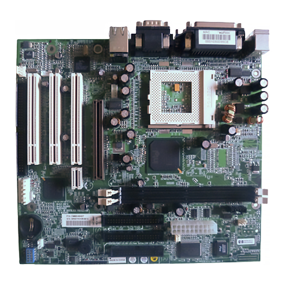
Chapter 2 System Components This chapter introduces the components of the motherboard. Major Components Audio CODEC PCI Slots AGP Slot PGA370 FW82815 Clock gen. GMCH DIMM Sockets FW82801AA Battery PC87360 BIOS Super I/O Figure 2-1. Major Components of System Board... -
Page 12: Table 2-1. Major Components Description
Reference Description Name Graphics Memory Controller Hub (GMCH) Controller Intel 82815 provides: (GMCH) Processor Interface: • - Supports Celeron or Pentium III (FC-PGA370) at 66/100/133MHz FSB - GTL+ Compliant host bus DRAM Interface: • - Supports SDRAM DRAM - Supports 512MB memory using x8, x16, x32, x64 x128, x256 and x512 64-bit SDRAM AGP Interface •... - Page 13 (Continued) Reference Description Name NS PC87360 Super I/O Control: • - An FDD controller for 360KB, 720KB, 1.2MB, 1.44MB and 2.88MB FDD - 3-mode FDD support - Keyboard controller - ECP/EPP mode support - High speed NS16C550 compatible serial port DIMM1, DIMM sockets: DIMM...
-
Page 14: Block Diagram
Block Diagram Intel Pentium III Proessor System Memory Intel Celeron Proessor DIMM1 DIMM2 System Bus (66/100/133 MHz) Intel 815 Chipset AGP Connector 64 Bit -AGP Graphies 100/133MHz 1X/2X/4X 66/133 MHz GMCH Graphies & Memory PCI1 PCI2 PCI3 -Display Cache Controller Hub) 133MHz -Memory Controller -AGP Controller... -
Page 15: Chapter 3 Connector And Jumper Definition
Chapter 3 Connector and Jumper Definition This chapter defines the connectors and jumpers on the motherboard. Figure 3-1. Connector and Jumper Locations... -
Page 16: Connector Definitions
Connector Definitions Internal Connectors Connector Definition J2, J3 DIMM sockets J5, J6, J7 PCI slots CPU fan ATX power System fan 1-2-3 Power LED HDD LED Power button 9-10 Keylock CPU socket ATX Riser AGP slot Battery Table 3-1. Internal Connector Definition External Connectors Connector Definition... -
Page 17: Jumper And Switch Settings
Jumper and Switch Settings NOTE: Jumpers not described in this chapter are reserved for factory use only. Do not change the default settings. Switch Setting (J24) On : Clear configuration Off : normal On : Clear password Off : normal On : Bootblock recovery enabled Off : Bootblock recovery disabled On : SW bootblock protection... -
Page 18: Chapter 4 Cpu And Memory Installation
Chapter 4 CPU and Memory Installation NOTE: To avoid damage during installation, you are advised to ask your dealer for help. NOTE: Static electricity can destroy electronic devices. Whenever you handle any option outside of its protective packaging, first discharge any static electricity from your body by touching a protective grounding device or unpainted metal on the rear panel of the system unit. -
Page 19: Figure 4-2. Installing Cpu
4. Press the arm downwards to the horizontal position. You will feel some resistance while doing so. This is normal as the pressure starts to secure the CPU in place. Figure 4-2. Installing CPU... -
Page 20: System Memory Installation
System Memory Installation 1. Locate the DIMM sockets (J2, J3) on the motherboard. AGP Slot DIMM Sockets DIMM Sockets Figure 4-3. DIMM Socket Locations 2. Align the DIMM module with the socket and firmly insert the DIMM into the socket. Then, push the plastic clips to snap it into place. Figure 4-4. -
Page 21: Chapter 5 The Setup Program
Chapter 5 The SETUP Program This chapter tells you how to configure your system using the SETUP program. Introduction The SETUP program allows you to enter the system configuration information. This information is needed by the system to identify the type of devices installed and to set up special features. -
Page 22: Table 5-1. Keyboard Usage In The Setup Program
The SETUP program contains five options: Main - Basic system configuration • Advanced - Detailed configuration besides basic system • configuration, including the configuration of internal chipset Boot - Boot sequence settings • Power - Power management settings • Exit - Exiting the SETUP program •... -
Page 23: Main
Main The “Main” option contains the basic configuration settings of the system. The followings describe in sequence all the items of this option. Date / Time The date and time might be incorrect when you start up your system for the first time. - Page 24 Memory Hole At 15M-16M This item, when enabled, turns system RAM off to free address space for use with an option card. 1MB extended memory gap, starting at 15MB, will be created in system RAM. Processor Serial Number The processor serial number is an electronic number incorporated into latest processors such as the Pentium III.
-
Page 25: Boot
Video Options This item allows you to define the video primary controller. Press [Enter] to go to the sub-menus for settings. Integrated I/O Ports This item allows you to configure the I/O devices and information, such as Serial port A, Serial port B and Parallel port. Press [Enter] to go to the sub-menus for settings. -
Page 26: Power
Power The “Power” option allows you to configure you system to save energy. The followings describe in sequence all the items of this category. State after Power Failure This item sets the state that your PC returns to after a power failure. If set to off, the PC will not boot after a power failure. -
Page 27: Exit
Exit To exit the SETUP program, you can choose Exit Saving Changes, Exit Discarding Changes or Load Default Values for all Settings from the “Exit” option. Exit Saving Changes After finished with your settings, you must save and exit SETUP so that the settings can take effect.
Need help?
Do you have a question about the 6515WU and is the answer not in the manual?
Questions and answers