Table of Contents
Advertisement
Quick Links
Table of Contents
Before You Begin............................................................................... iii
1
Introduction ................................................................................ 1
1.1
Unpacking.................................................................................... 1
1.2
Features........................................................................................ 2
1.3
Major Components ....................................................................... 4
1.4
Setup Guidelines .......................................................................... 5
2
Jumpers and Connectors ............................................................ 7
2.1
Jumper Definitions ....................................................................... 7
2.2
Connector Definitions................................................................... 9
3
Hardware Installation............................................................... 13
3.1
Installing Memory Modules........................................................ 13
3.2
Installing CPU............................................................................ 14
3.3
Installing Expansion Cards ......................................................... 15
4
BIOS Setup................................................................................ 17
4.1
Using BIOS Setup ...................................................................... 17
4.2
Main Menu................................................................................. 19
4.3
Advanced Menu ......................................................................... 20
4.4
Security Menu ............................................................................ 26
4.5
PC Health Menu ......................................................................... 28
4.6
Power Menu ............................................................................... 29
4.7
Boot Menu ................................................................................. 31
4.8
Exit Menu .................................................................................. 33
4.9
BIOS Reference - POST Codes.................................................. 35
4.10 Updating BIOS (Flash Utility) .................................................... 42
5
Software Installation ................................................................. 45
5.1
Installation Instructions for Windows® 98/2000/Me/XP............. 45
i
Advertisement
Table of Contents

Related Manuals for MiTAC 6813BU


Summary of Contents for MiTAC 6813BU
-
Page 1: Table Of Contents
Table of Contents Before You Begin................iii Introduction ................1 Unpacking..................1 Features..................2 Major Components ............... 4 Setup Guidelines ................5 Jumpers and Connectors ............7 Jumper Definitions ............... 7 Connector Definitions..............9 Hardware Installation............... 13 Installing Memory Modules............13 Installing CPU................ -
Page 3: Before You Begin
Before You Begin About This Manual This manual introduces your motherboard, or called system board, and tells you how to set it up for operation. It is divided into the following chapters: Chapter 1, Introduction, introduces the product features and major components. -
Page 4: Safety Precautions
Safety Precautions To protect the motherboard and other components against damage from static electricity, you should follow these guidelines whenever you handle electrical components: Disconnect the AC power cord from the electrical outlet before you work on the inside of the computer. Hold a component by its edge and avoid touching the IC chips, leads, or circuitry. -
Page 5: Introduction
Introduction 1.1 Unpacking After unpacking the shipping carton, you should find these standard items: Motherboard Driver and User’s Manual CD Cable Kit Inspect all the items. If any item is damaged or missing, notify your dealer immediately. -
Page 6: Features
1.2 Features This motherboard utilizes state-of-the-art technologies to meet the users’ needs and can be easily upgraded to meet any future demands. The motherboard features: Form factor Micro ATX (9.6” x 9.6”) CPU socket uPGA478 Pentium 4 socket to support Intel® Pentium 4 processor at 400 MHz or Northwood processor at 400 MHz data bus Chipset Intel®... - Page 7 Audio controller AC’97 2.1-compatible stereo audio codec: – SigmaTel STAC9750T or – Analog Device AD1981A or – Analog Device AD1885 LAN controller (option) PCI Ethernet controller is fully-compliant with 10Base-T and 100Base-TX specifications and IEEE 802.3 standard: – Intel 82562ET or –...
-
Page 8: Major Components
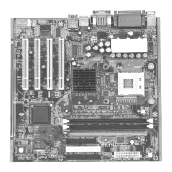
1.3 Major Components... -
Page 9: Setup Guidelines
This section identifies the major controllers on the motherboard. Reference Description NS DP83816 PCI Ethernet controller (option) SigmaTel STAC9750T / Analog Device AD1981A / Analog Device AD1885 AC97 audio codec Intel 82562ET–10/100 Mbps platform LAN connecting device (option) System Clock Generator Intel Brookdale-GL Memory Controller Hub (GMCH) uPGA478 socket to support Intel®... - Page 10 5. Install the power supply, hard disk drive, CD-ROM drive, and floppy disk drive. 6. Connect one end of each signal cable to the corresponding connector on the motherboard and the other end to the installed device. See section 2.2 for details.
-
Page 11: Jumpers And Connectors
Jumpers and Connectors 2.1 Jumper Definitions A jumper is a set of two or more pins on the motherboard. You use a jumper cap to cover (short) the pins for selecting a hardware setting. Jumpers with more than two pins have numbers imprinted on the motherboard to identify the pins. - Page 12 Jumper Definition Setting Description CMOS setting Normal Clear CMOS To clear the RTC and CMOS RAM, set J17 to 2-3 for one second and set it back to 1-2 again. Password setting Open Normal Short Clear password...
-
Page 13: Connector Definitions
2.2 Connector Definitions CAUTION: When connecting the power connectors to the motherboard, make sure that the computer is not connected to an electrical outlet. CAUTION: When connecting a signal cable (also called ribbon cable), pin 1 of the cable should be aligned with pin 1 of the connector on the motherboard. Pin 1 side of the cable is identified by a color, usually red, stripe. -
Page 14: Internal Connectors
Internal Connectors Connector Definition Description Battery This is the socket for the RTC battery. DDR1/ DIMM These are the two sockets for the memory modules. DDR2 sockets See section 3.1 for installation instruction. This connects the audio cable from the CD-ROM CD-in drive. - Page 15 Connector Definition Description Pin 1, 3, The USB ports connect USB devices. 5, 7 Pin 13, 15 Phone-in This connects an external headphone. Pin 19 MIC-in This connects an external microphone. NOTE: For each of these ports to be available, you must connect a signal cable from the connector to their respective ports on the front panel.
-
Page 16: External Connectors
External Connectors Connector Definition Description This parallel port connects a parallel device. (upper) This connects an external VGA display monitor. (lower) The USB ports connect USB devices. Line-in This line-in port connects an audio device such as Hi- (left) Fi set, radio set, CD player, synthesizer, walkman, etc. Line-out This lineout port connects an audio device such as a (middle) -
Page 17: Hardware Installation
Hardware Installation CAUTION: Make sure that the power is turned off and the power cord is disconnected before installing hardware devices. Leaving the power on can cause serious damage to your system. 3.1 Installing Memory Modules Your motherboard has two sockets supporting DDR-SDRAM 200/266 unregistered 184-pin non-ECC DIMMs (single and double-sided). -
Page 18: Installing Cpu
3.2 Installing CPU Your system board provides ZIF Socket uPGA478. 1. Find the ZIF socket (Socket uPGA478) on the motherboard (see page 9). 2. Lift the ZIF socket arm up to the vertical position. 3. Align the CPU so its Pin 1 corner (beveled corner) is at the Pin 1 corner of the ZIF socket. -
Page 19: Installing Expansion Cards
5. Install the CPU fan (see manufacturer’s instructions that came with the fan). 6. Connect the fan cable to J14 (see page 9). CAUTION: The CPU cooling fan must be installed, otherwise the CPU and/or motherboard will overheat and be damaged. 3.3 Installing Expansion Cards Your motherboard contains four PCI slots. -
Page 21: Bios Setup
BIOS Setup 4.1 Using BIOS Setup The BIOS Setup program allows you to enter the system configuration information. This information is needed by the system to identify the type of devices installed and to set up special features. The configuration information is stored in a special kind of memory called CMOS (Complementary Metal Oxide Semiconductor) RAM. - Page 22 Description Move the highlight to the previous or the next item. Move the highlight to the previous or next option. Page Up/+, Cycle through the pre-defined values for the selected item. Pressing Page Up or + brings up the next value; pressing Page Down/−...
-
Page 23: Main Menu
4.2 Main Menu The “Main” Setup menu contains the basic configuration settings of the system. Date (mm:dd:yy) The date format is <month> <date> <year>. Time (hh:mm:ss) The time format <hour> <minute> <second> is based on a 24-hour military- time clock format. System information on the following items is also listed. -
Page 24: Advanced Menu
4.3 Advanced Menu The “Advanced” Setup menu contains the input/output configuration settings of the system. Reset Configuration Data Normally, you would leave this field disabled. Select Enabled to reset the Extended System Configuration Data (ESCD) when you exit Setup if you have installed a new add-on device and the system reconfiguration has caused such a serious conflict of resources that the operating system cannot boot. - Page 25 Spread Spectrum This item allows you to take advantage of the center spread-type or down spread-type of spread spectrum. Integrated Peripherals Enter Press to go to a submenu that allows you to configure the on-board device controllers (I/O, IRQ, and DMA assignment). USB Controller This item allows you to enable or disable support for Legacy USB devices in non-USB-aware operating systems like DOS.
-
Page 26: Onboard Parallel Port
AC97 Audio Selecting Enabled allows BIOS to detect whether you are using any AC97 audio codec device. If an AC97 audio codec device is detected, the on-board AC97 audio controller will be enabled; if no AC97 audio codec device is detected, the on-board AC97 audio controller will be disabled. -
Page 27: Ide Configuration
IDE Configuration Enter Press to go to a submenu that allows you to select the IDE controller and hard disk drive type installed in your system. Primary IDE Controller Secondary IDE Controller This item allows you to enable or disable the primary and secondary IDE controller. - Page 28 Enter When you press for the “IDE HDD Auto-Detection” item, the remaining fields on this menu will be filled if the detection is successful. For the IDE Primary/Secondary Master/Slave item, select Manual only if you wish to manually enter the parameters such as number of cylinders, number of heads, landing zone, write precompensation, and number of sectors/tracks.
-
Page 29: Diskette Configuration
The PIO Mode item sets the mode timing according to the IDE hard disk drives in your system. Rather than have the BIOS issue a series of commands to effect a transfer to or from the disk drive, PIO (Programmed Input/Output) allows the BIOS to tell the controller what it wants and then let the controller and the CPU perform the complete task by them. -
Page 30: Floppy 3 Mode Support
Drive A Each of these items sets the type of floppy disk drive in your system. None No floppy disk drive installed. 360K, 5.25 in 5-1/4 inch PC-type standard drives; 360-KB capacity. 1.2M, 5.25 in 5-1/4 inch AT-type high density drive; 1.2 MB capacity. -
Page 31: Set Supervisor Password
Supervisor Password Is This item shows if a supervisor password has been set. The password is required for accessing the BIOS Setup program if both Supervisor Password Is and the next User Password Is item was set. User Password Is This item shows if a user password has been set. -
Page 32: Shutdown Temperature
4.5 PC Health The “PC Health” Setup menu allows you to monitor the operating status of your system. Shutdown Temperature This item allows you to set up the CPU shutdown temperature. The following items on your system are monitored: Remote1 Temperature Remote2 Temperature Ambient Temperature VCore (From VID) -
Page 33: Power Menu
4.6 Power Menu The “Power” Setup menu contains the power management settings that help save system power. ACPI Suspend Type This item allows you to set whether the ACPI Suspend Mode is S1 or S3-type. NOTE: The S1 sleeping state is a low wake-up latency sleeping state. In this state, no system context is lost (CPU or chipset) and hardware maintains all system contexts. -
Page 34: Pwron After Pwr-Fail
PWRON After PWR-Fail This item defines the state of your computer when power is restored after an unexpected power interruption. Former-Sts System restores itself to its former state before power failed. System will power on when power is restored. System remains in the power-off state until you press the power button of your system cabinet. -
Page 35: Boot Menu
4.7 Boot Menu The “Boot” Setup menu sets the sequence of the devices to be searched for the operating system. Quiet Boot This item when disabled allows the display of normal POST messages during system boot. When enabled, system displays OEM logo instead of POST messages. -
Page 36: Hard Disk Boot Priority
1st Boot Device 2nd Boot Device 3rd Boot Device 4th Boot Device These items set the sequence of booting, i.e., which drive to search first for the operating system. Hard Disk Boot Priority Enter Press to go to a submenu that allows you to select the hard disk boot device priority. -
Page 37: Exit Menu
4.8 Exit Menu The “Exit” Setup menu allows you to leave the BIOS Setup program. After you are finished with your settings, you must save and exit so that the new settings can take effect. Exit Saving Changes After finishing with your settings, you must save and exit Setup so that the changes you have made can take effect. -
Page 38: Save Custom Defaults
Save Custom Defaults This option allows you to save the current BIOS settings to the system’s flash ROM. Discard Changes This option allows you to restore the previous values for all the BIOS Setup items. -
Page 39: Bios Reference - Post Codes
4.9 BIOS Reference – POST Codes NOTE: ISA POST codes typically output to the port address 80h. POST (hex) Description Test CMOS R/W functionality. Early chipset initialization: – Disable shadow RAM – Disable L2 cache (socket 7 or below) – Program basic chipset registers. Detect memory –... - Page 40 POST (hex) Description Test F000h segment shadow to see whether it is R/W-able or not. If test fails, keep beeping the speaker. Reserved Auto-detect flash type to load appropriate flash R/W codes into the run time area in F000 for ESCD and DMI support. Reserved Use walking 1’s algorithm to check out interface in CMOS circuitry.
- Page 41 POST (hex) Description Early PCI initialization: – Enumerate PCI bus number – Assign memory and I/O resource – Search for a valid VGA device and VGA BIOS and put it into C000:0. 1. If Early_Init_Onboard_Generator is not defined on-board clock generator initialization.
- Page 42 POST (hex) Description Reserved Reserved Test 8254. Reserved Test 8259 interrupt mask bits for channel 1. Reserved Test 8259 interrupt mask bits for channel 2. Reserved Reserved Test 8259 functionality. Reserved Reserved Reserved Initialize EISA slot. Reserved 1. Calculate total memory by testing the last double word of each 64 K page.
- Page 43 POST (hex) Description Reserved 1. Display PnP logo. 2. Early ISA PnP initialization – assign CSN to every ISA PnP device. Reserved Initialize the combined Trend anti-virus code. Reserved (Optional feature) show message for entering AWDFLASH.EXE from FDD. Reserved 1. Initialize Init_Onboard_Super_IO. 2.
- Page 44 POST (hex) Description Reserved Reserved Reserved Reserved Reserved Detect and install all IDE devices: HDD, LS-120, ZIP, CD-ROM, etc. (Optional) Enter AWDFLASH.EXE if: – AWDFLASH.EXE is found in floppy drive – ALT+F2 is pressed. Detect serial and parallel ports. Reserved Reserved Detect and install coprocessor.
- Page 45 POST (hex) Description 1. Assign IRQs to PCI devices. 2. Set up ACPI table at top of memory. Reserved 1. Invoke all ISA adapters ROMs. 2. Invoke all PCI ROMs (except VGA). Reserved 1. Enable/disable parity checks according to CMOS Setup. 2.
-
Page 46: Updating Bios (Flash Utility)
4.10 Updating BIOS (Flash Utility) You can use the following utility to update the BIOS as the BIOS version is changed. It allows your system to have the most updated functions and compatibility. Preparation The upgrade process requires two files: The new BIOS file (e.g., newbios.bin) from your dealer The upgrade utility (awdflash.exe) from Award Software, Inc. - Page 47 Enter At the DOS command line, type awdflash and press A sequence of prompts will ask you to type data: 1. File Name to Program: Enter Type the name of the new BIOS file (e.g., newbios.bin) and press 2. Do You Want to Save BIOS (Y/N)? At the bottom of the menu, this prompt appears: Enter If you DO NOT wish to save the old BIOS, type N and press...
-
Page 49: Software Installation
The chipset driver is required for using your system’s Intel® Brookdale-GL chipset capabilities. To install this driver, follow these steps: 1. Insert the driver CD into the CD-ROM drive. 2. Run the SETUP.EXE program in the \6813bu\chipset\ directory on the CD. 3. Follow the onscreen instructions to complete the installation. -
Page 50: Vga Driver
SigmaTel STAC9750T chip – \6813bu\Audio\sigmatel\win98 (for Windows 98) \6813bu\Audio\sigmatel\winme (for Windows Me) \6813bu\Audio\sigmatel\win2K (for Windows 2000) \6813bu\Audio\sigmatel\winxp (for Windows XP) or when motherboard contains Analog Device AD1981A/AD188 chip – \6813bu\Audio\AD\win98 (for Windows 98) \6813bu\Audio\AD\winme (for Windows Me) \6813bu\Audio\AD\win2K (for Windows 2000) \6813bu\Audio\AD\winxp (for Windows XP). - Page 51 LAN Driver (option) NOTE: Have your Windows 98/Me/XP/2000 Installation CD available in case you are prompted for them when you install the new adapter. 1. After connecting the LAN cable, ensure that Windows 98/Me/XP/2000 is up and running properly. 2. Insert the CD into the drive. 3.
- Page 52 Intel DA82562ET chip – \6813bu\LAN\Intel\win98 (for Windows 98) \6813bu\LAN\Intel\winme (for Windows Me) \6813bu\LAN\Intel\win2K (for Windows 2000) \6813bu\LAN\Intel\winxp (for Windows XP) or when motherboard contains NS DP83816 chip – \6813bu\LAN\NS\win98 (for Windows 98) \6813bu\LAN\NS\winme (for Windows Me) \6813bu\LAN\NS\win2K (for Windows 2000) \6813bu\LAN\NS\winxp (for Windows XP).
- Page 53 3. Under the item “USB Device,” double-click or right-click on “USB Hub” to enter “Properties.” 4. Click on the “Driver” tab. 5. Click on “Update Driver,” then click on “Have Disk” and choose the following directory \6813bu\USB\. 6. Follow the onscreen instructions to complete the installation.
Need help?
Do you have a question about the 6813BU and is the answer not in the manual?
Questions and answers