Atlona OmniStream AT-OMNI-121 Manual
Single-channel / dual-channel networked av decoder
Hide thumbs
Also See for OmniStream AT-OMNI-121:
- Manual (139 pages) ,
- Solutions setup and configuration manual (62 pages) ,
- Deployment manual (19 pages)

Related Manuals for Atlona OmniStream AT-OMNI-121


Summary of Contents for Atlona OmniStream AT-OMNI-121
- Page 1 OmniStream ™ Single-Channel / Dual-Channel Networked AV Decoder AT-OMNI-121 Atlona Manuals AT-OMNI-122 Networked AV...
- Page 2 Version Information Version Release Date Notes 04/17 Initial release 06/17 New enclosure, documentation updates: AMS interface; front-panel buttons, decoder set tab 12/17 Video wall configuration plus bezel compensation, slate / logo insertion, text insertion, redundancy grace period for IP input changes 05/18 Updated to reflect AMS 2.0 07/18...
- Page 3 Welcome to Atlona! Thank you for purchasing this Atlona product. We hope you enjoy it and will take a extra few moments to register your new purchase. Registration only takes a few minutes and protects this product against theft or loss. In addition, you will receive notifications of product updates and firmware.
- Page 4 Atlona requires that products returned are properly packed, preferably in the original carton, for shipping. Cartons not bearing a return authorization or case number will be refused. Atlona, at its sole discretion, reserves the right to reject any products received without advanced authorization. Authorizations can be requested by calling 1-877-536-3976 (US toll free) or 1-408- 962-0515 (US/international) or via Atlona’s website at www.atlona.com.
- Page 5 Damage, deterioration or malfunction resulting from the installation or removal of this product from any installation, any unauthorized tampering with this product, any repairs attempted by anyone unauthorized by Atlona to make such repairs, or any other cause which does not relate directly to a defect in materials and/or workmanship of this product.
- Page 6 The information bubble is intended to alert the user to helpful or optional opera- product. tional instructions in the literature accompanying the product. 11. Only use attachments/accessories specified by Atlona. 1. Read these instructions. 12. To reduce the risk of electric shock and/or damage 2. Keep these instructions.
-
Page 7: Table Of Contents
Table of Contents Introduction Features Package Contents Panel Description AT-OMNI-121 AT-OMNI-122 Installation RS-232 Connections IR Connections Audio Connectors Connection Instructions Connection Diagram Configuration Discovery using AMS Accessing Decoders in AMS Configuring a Static IP Address Basic Operation LED Indicators Rebooting OmniStream ID Button Broadcast Messaging Reset to Factory-Default Settings. - Page 8 Table of Contents Serial Port Serial Configuration Command Text page Color Location Size Logo page PTP page Network page The Virtual Matrix Appendix Updating the Firmware FEC Details Matrix Size, Overhead, and Latency FEC and Video Bitrate FEC, Latency, and Lip Sync Mounting Instructions Rack Tray for OmniStream Specifications...
-
Page 9: Introduction
Introduction The Atlona OmniStream™ 121 (AT-OMNI-121) is a networked AV decoder for one HDMI source up to 4K/UHD, plus embedded audio and RS-232 control. The Atlona OmniStream™ 122 (AT-OMNI-122) adds a second channel of encoding for two HDMI sources up to 4K/UHD and RS-232 control and can deliver duplicate AV streams to two networks for full system redundancy in mission-critical applications. -
Page 10: Panel Description
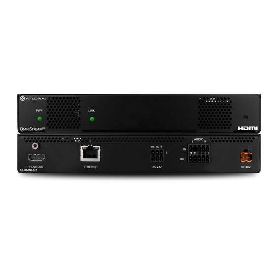
Panel Description AT-OMNI-121 LINK LINK TREAM Front AUDIO TREAM RX TX AUDIO RX TX ETHERNET RS-232 HDMI OUT DC 48V AT-OMNI-121 ETHERNET RS-232 HDMI OUT DC 48V AT-OMNI-121 Rear RS-232 This LED indicator is green when the unit is Use the included Phoenix terminal block to powered. -
Page 11: At-Omni-122
Panel Description AT-OMNI-122 LINK TREAM LINK Front TREAM RX TX RX TX HDMI OUT ETHERNET RS-232 AUDIO DC 48V AT-OMNI-122 HDMI OUT ETHERNET RS-232 DC 48V AUDIO AT-OMNI-122 Rear ETHERNET 1 / ETHERNET 2 This LED indicator is green when the unit is Connect Ethernet cables from these ports to the powered. -
Page 12: Installation
Installation RS-232 Connections Both the AT-OMNI-121 and AT-OMNI-122 provide RS-232 over IP, allowing communication between an automation system and an RS-232 device. This step is optional. Note that different Phoenix connectors are provided with each product. 1. Use wire strippers to remove a portion of the cable jacket. 2. -
Page 13: Ir Connections
Unit GND (black) SIGNAL (white/black) TX out The following components are required. Note that other components may also be used. However, Atlona has tested and verified the following components for this application: • Xantech CB12 1 Zone Connecting Block •... - Page 14 Installation For downstream IR control, either multicast or unicast mode can be used. However, when controlling a source from the decoder (viewing location), unicast mode should be used. Refer to Unicast Mode (page 25) Multicast Mode (page 27) for more information. AT-OMNI-IR-TX SIGNAL GROUND...
-
Page 15: Audio Connectors
Installation Audio Connectors In addition to passing audio directly from the encoder to the decoder, both the AT-OMNI-121 and AT-OMNI-122 provide two additional audio options. Either option can be used or they can be used simultaneously. • HDMI audio can be de-embedded and output to two-channel analog audio. •... - Page 16 NOTE: Unblanaced XLR audio pins require Pin 1 and Pin 3 to be connected. IMPORTANT: When using analog audio inputs on the OmniStream decoder, the decoder must be powered using the 48V power supply (AT-PS-48083-C). This power supply is sold separately and can be purchased from Atlona. AT-OMNI-121 / AT-OMNI-122...
-
Page 17: Connection Instructions
IMPORTANT: When using analog audio inputs on the OmniStream decoder, the decoder must be powered using the 48V power supply (AT-PS-48083-C). This power supply is sold separately and can be purchased from Atlona. 5. IR (optional) NOTE: For dual-channel decoders, only the RS-232 2 port supports both serial and IR. Single- channel decoders only support IR on the RS-232 2 port. -
Page 18: Connection Diagram
Installation Connection Diagram Blu-ray Player Automation Control System CT OR RE SE 48 V IN PU DI SP M NI AT-OMNI-112 Projector AT-OMNI-122 M NI AT-OMNI-121 / AT-OMNI-122... -
Page 19: Configuration
By default, the decoders are set to DHCP mode, allowing a DHCP server (if present) to assign the decoder an IP address. Once an IP address has been assigned, the Atlona Management System (AMS) can be used to manage the product on the network. - Page 20 Configuration 6. Click Devices from the fly-out menu. 7. Click the Unassigned option. All available decoders will be displayed under the Unassigned category. When a decoder is unassigned, it means that it has not been assigned to a site, building, and/or room. Refer to the AMS User Manual for more information on these topics.
- Page 21 Configuration 8. Click the desired decoder from the Unassigned device list. Once the unit is selected, the control interface for the encoder will be displayed. The illustration below shows the DEVICE INFO screen for an AT-OMNI-122 decoder. AT-OMNI-121 / AT-OMNI-122...
-
Page 22: Configuring A Static Ip Address
Configuration Configuring a Static IP Address The following section is only required to set the decoder, currently in Auto IP mode, to a static IP address. If a DHCP server is not found within 60 seconds, encoders are automatically placed in Auto IP mode and will be assigned an IP address within the range 169.254.xxx.xxx. -
Page 23: Basic Operation
PoE, the PWR indicator will be green. • Check the Ethernet cable for possible damage or loose connections. • Connect the optional 48V DC power supply (available from atlona. com) to the encoder. When using an external power supply, the PWR indicator will be red. •... -
Page 24: Rebooting Omnistream
Basic Operation Rebooting OmniStream To reboot the OmniStream decoder, press and release the recessed button, on the far-right side of the unit, using a small, pointed object. Rebooting the decoder does not reset the decoder to factory-default settings. LINK TREAM RX TX ID Button HDMI OUT... -
Page 25: Unicast Mode
Basic Operation Unicast Mode The term unicast is used to describe a configuration where information is sent from an encoder to a single decoder. Although it is common to have multiple encoder and decoder units within a system, it may also be desirable to restrict a single encoder to communicate with one decoder. - Page 26 Basic Operation 5. Go to the decoder AMS interface. 6. Click IP INPUT from the menu. 7. Remove the IP address from the Multicast Address field. 8. Click the SAVE button to commit changes. Field should be blank 9. Unicast setup is complete. The decoder unit will now receive streams exclusively from the encoder containing the IP address of this decoder.
-
Page 27: Multicast Mode
Basic Operation Multicast Mode The term multicast is used to describe a configuration where information is sent from one or more points to a set of other points. For example, a single encoder can transmit data to multiple decoders. In addition, if multiple encoders are used, each encoder can stream data to any decoder that is not already receiving data from an encoder. - Page 28 Basic Operation AT-OMNI-121 / AT-OMNI-122...
-
Page 29: Configuring Audio Output
IMPORTANT: When using analog audio inputs on the OmniStream decoder, the decoder must be powered using the 48V power supply (AT-PS-48083-C). This power supply is sold separately and can be purchased from Atlona. De-embedding Audio De-embedding audio will extract the HDMI audio and automatically downmix to two-channel analog audio, using the included captive-screw connectors. -
Page 30: Embedding Audio
Basic Operation Embedding Audio Embedding audio will replace the existing HDMI audio source, normally heard on the output of the decoder. The analog audio will be heard on the HDMI OUT port of the decoder. 1. Connect the power supply to the DC 48V connector on the decoder. 2. -
Page 31: Control Using Rs-232 Commands
Basic Operation Control Using RS-232 Commands RS-232 data can be sent over IP using one of two methods: • Triggering stored commands, directly from the decoder unit. • Using the TCP proxy feature. Both methods will be discussed in this section. NOTE: When configuring RS-232, always make sure to configure the correct baud rate, data bits, parity bit, stop bits, and flow control settings, as required by the connected device. -
Page 32: 802.1X Authentication
NOTE: As of this writing, AMS does not currently support 802.1X configuration. This will be added in a future release of AMS. Contact Atlona for more information. Use the following instructions to set up video mode using the OmniStream web GUI. -
Page 33: Eap-Tls Protocol
Username: admin Password: Atlona 4. Click the Continue button, or press the ENTER key, to continue. 5. Click Network in the menu bar, near the top of the page. 6. Click the 802.1x Mode drop-down list and select EAP-TLS. - Page 34 Basic Operation 7. Three additional fields will be displayed: Client certificate, Client private key, and CA certificate. Provide the required information in each field. 8. Click the SAVE button near the bottom of the page. If using dual-channel decoders, both Network 1 and Network 2 (both Ethernet ports) will need to be set up, depending upon the system requirements.
-
Page 35: Peap/Mschapv2 Protocol
Username: admin Password: Atlona 4. Click the Continue button, or press the ENTER key, to continue. 5. Click Network in the menu bar, near the top of the page. 6. Click the 802.1x Mode drop-down list and select PEAP/MSCHAPv2. - Page 36 Basic Operation 7. Three additional fields will be displayed: Identity, Password, and CA certificate. Provide the required information in each field. 8. Click the SAVE button near the bottom of the page. If using dual-channel decoders, both Network 1 and Network 2 (both Ethernet ports) will need to be set up for, depending upon the system requirements.
-
Page 37: Aes67 Audio
NOTE: As of this writing, AMS does not currently support AES67 configuration. This will be added in a future release of AMS. Contact Atlona for more information. Use the following instructions to set up video mode using the OmniStream web GUI. -
Page 38: Ir Configuration
Basic Operation IR Configuration NOTE: For dual-channel decoders, only the RS-232 2 port supports both serial and IR. Single- channel decoders only support IR on the RS-232 2 port. The IR emitter or IR receiver must be connected to this port. Refer to IR Connections (page 13) for wiring information. - Page 39 Basic Operation 6. Click the SAVE button, in the Serial Port 2 section to commit changes. 7. Scroll down and locate the Serial Configuration 2 section. 8. Click the Interface drop-down list and select the desired interface. 9. Enter the IP address, in the Destination IP Address field, where the IR data will be sent. 10.
-
Page 40: Scrambling
Basic Operation Scrambling OmniStream supports 128-bit Advanced Encryption Standard (AES) scrambling for both audio and video streams. Scrambling can be enabled or disabled through AMS, and can be individually applied to video, audio, or both. Scrambling can be enabled either before or after the decoding process is started. Data streams cannot be scrambled;... -
Page 41: Using The Virtual Matrix
Basic Operation 3. Enter the desired scrambling key in the Key field. NOTE: If a user-defined key is specified, then it must be a minimum of eight alphanumeric characters. Special characters and spaces are not permitted. 4. Click the Save button at the bottom of the page to commit the changes. Using the Virtual Matrix 1. - Page 42 Basic Operation 5. Enter the desired scrambling key using one of the following methods: • Manual enter a user-defined key in the Key field. • Click the icon to generate a random key using AMS. Each time this icon is clicked, a new scrambling key will be generated.
-
Page 43: Setting The Video Mode
Basic Operation Setting the Video Mode OmniStream offers two video modes: Video and PC application. These two modes will optimize the image, based on the type of information that is being displayed. Use the Video mode when display motion graphics/video. Set this mode to PC application when viewing static images, such as spreadsheets or similar content. -
Page 44: Slate / Logo Insertion
Basic Operation Slate / Logo Insertion Slate / logo insertion is managed from within AMS. The difference between a “slate” and “logo” is in the size of the image and how it is used: Logos are classified as smaller, low-resolution images that can be positioned at specified locations on the screen. -
Page 45: Deleting Slates / Logos
Basic Operation NOTE: If the selected image will be used as a logo, then proceed with Steps 7 through 9. If the image will be used as a slate, skip to Step 10. 7. Click the logo from the Select Logo drop-down list. To prevent the image from being displayed, select the Not used option. -
Page 46: Text Insertion
Basic Operation Text Insertion NOTE: Text Insertion is only supported when the frame rate conversion is set to sub-frame latency mode. To set the frame rate conversion mode, go to the HDMI Output menu and select Sub Frame Latency from from the Frame Rate Conversion drop-down list. 1. - Page 47 Basic Operation 9. Specify the size of the text in the Width (%) and Height (%) fields. Each of these values is based on the horizontal and vertical resolution of the screen. 10. Click the SAVE button to apply all changes. AT-OMNI-121 / AT-OMNI-122...
-
Page 48: Creating Video Walls
Basic Operation Creating Video Walls The following example illustrates how to configure a 2x2 video wall. Below, four decoders are subscribed to a single encoder and are displaying the same image on all four displays. The video source is 3840 x 2160. In order to create a single image using all four displays, each source image will need to be cropped and scaled to one-fourth of the total image resolution. - Page 49 Basic Operation 3. Locate the Resolution option, in the Video section, and select 1920x1080. This will scale the output resolution from each decoder to 1920x1080. 4. Click the Stretch/Crop Mode drop-down list and select fullscreen. This guarantees that the image will fill the screen.
- Page 50 Basic Operation 5. Click the Enable toggle to activate the Video wall option. Once enabled, the Video wall section will be expanded and display all available options. 6. Enter the horizontal and vertical resolution of the display in the Width and Height fields. This is the size of the source to be used for this window of the video wall.
- Page 51 Basic Operation 7. Enter the number of video wall rows in the Horizontal field and the number of columns in the Vertical field. These values are the pixel start position (upper left most pixel). The table below, lists left and right coordinates for a 2x2 video wall, with the specified source resolution.
- Page 52 Basic Operation The image on Display 1, as shown below, has been cropped and rotated and now is displayed correctly. 9. Click the SAVE button at the bottom of the screen to accept changes. 10. Repeat steps 1 through 9 for decoders 2, 3, and 4. Note that in this example, at Step 10, decoders 3 and 4 will not require any rotation.
- Page 53 Basic Operation Once all four decoders have been properly configured, the image will be correctly displayed across all four displays: Encoder Decoder Decoder Decoder Decoder Display Wall 11. Check the image, on each display, and make sure they are aligned correctly with the other images on the video wall.
-
Page 54: Bezel Compensation
Bezel compensation can be adjusted at any time. The illustration on the left shows a simple 2x2 video wall without bezel compensation. Note how the Atlona logo is stretched, horizontally. On the right, bezel compensation is used to correct the “distorted” image. -
Page 55: Using Velocity
Using Velocity™ The following section provides instructions on creating and using video walls with the Atlona Velocity Control Software. Familiarity with the Velocity software is assumed. Refer to the Atlona Velocity User Manual for more information, if necessary. 1. Launch a web browser and enter the IP address of AMS, in the address bar. - Page 56 9. The Technology fly-out menu will be display. 10. In the fly-out menu, click Miscellaneous > Atlona > to expand the Atlona technology menu. 11. Click the Quick Add button for Velocity Video Wall: VELOCITY-VIDEO-WALL. The video wall technology will be added to the room.
- Page 57 Basic Operation 12. Scroll down to the bottom of the page and locate the Velocity Video Wall driver. 13. Click the Edit icon. This icon is represented by a pencil. 14. The Video Wall / Pixel Space Dimensions dialog will be displayed.
- Page 58 Basic Operation c. To create a custom size for the video wall, enter the desired dimensions under the Custom section. Enter the width and height directly, or use the spinner controls at the far end of each field, to adjust the values.
- Page 59 To reposition displays, click and drag them to the appropriate places, within the Pixel Space window. Note that each display is identified with a name and an IP address, in the upper-left corner. Refer to the Atlona Velocity User Manual for more information on naming devices.
- Page 60 Basic Operation 18. Click the Lock Displays icon in the menu bar of the Pixel Space window. This is optional. However, enabling this feature will prevent accidental repositioning of the displays, during the configuration procedure. When locked, this icon will turn red. To unlock the displays (for adjustment purposes), click the Lock Displays icon again.
- Page 61 Release the mouse to commit the changes. Refer to the Atlona Velocity User Manual for more information on manipulating source windows. NOTE: When source windows are resized, they will “snap” to the nearest vertical or horizontal border, depending upon the direction that the mouse cursor is being moved.
- Page 62 25. Repeat steps 21 through 23 to create the preset. Once the desired presets have been created, click the preset name under the Presets section to recall it. The video wall will be updated with the selected preset. Refer to the Atlona Velocity User Manual for more information on using and recalling presets. AT-OMNI-121 / AT-OMNI-122...
-
Page 63: Configuring Redundant Streams
Basic Operation Configuring Redundant Streams OmniStream decoders have the ability to identify missing streams, should an input be disconnected from the encoder, and will recover the image almost instantaneously. The decoder can access the same stream from two separate multicast addresses and switch between them, when necessary. 1. -
Page 64: Redundancy Grace Period
Basic Operation Redundancy Grace Period During use, the decoder can be switched to another multicast stream. However, if the decoder encounters a missing stream, during the switch and when redundancy is enabled, then this will cause the decoder to automatically failover to the multicast source configured as the backup. -
Page 65: The Ams Interface
The AMS Interface Device Info page The Device Info page provides general information about the decoder. Alias Enter a name for the unit in this field. This is optional. Model The model number of the unit. Model Description AT-OMNI-121 Single-channel decoder AT-OMNI-122 Dual-channel decoder AT-OMNI-121 / AT-OMNI-122... - Page 66 The AMS Interface IP Address 1 / IP Address 2 Displays the IP address of the ETHERNET 1 and ETHERNET 2 ports, respectively. Single-channel encoders will only have a single IP address. MAC Address 1 / MAC Address 2 Displays the MAC address of the ETHERNET 1 and ETHERNET 2 ports, respectively. Single-channel encoders will only have a MAC address.
- Page 67 The AMS Interface FACTORY RESET Click this button to reset the encoder to factory-default settings. When performing a factory reset, the following options can be selected, by clicking the check box. If no options are selected, then the encoder is reset with no factory-default settings.
-
Page 68: Sap Page
The AMS Interface SAP page The SAP page enables or disables the Session Announcement Protocol protocol. Enabling SAP configures the decoder to look for SAP messages from encoders on the network that are configured to send SAP. Any messages that are discovered will be displayed here. Enabled Click this toggle switch to enable or disable SAP. -
Page 69: Ip Input Page
The AMS Interface IP Input page The IP Input tab provides configuration of each input, the assigned multicast address(es), and ports. Name The name used by AMS to identify the IP input. Enable Click this checkbox to enable the IP input. Interface Select the physical interface, that will be used to carry the multicast traffic, from this drop-down list. - Page 70 The AMS Interface Mode Click this drop-down list to select the mode. Mode can be set to exclude or include and is specifically used when using Source Specific Multicast (SSM). SSM will only function if the network is properly set up to support it. Mode Description exclude...
-
Page 71: Hdmi Output Page
The AMS Interface HDMI Output page The HDMI Output tab provides options to configure the output streams. Output Name The name used by AMS to identify the HDMI output. Enabled Click this toggle switch to enable or disable scrambling on the decoder. When enabled, the toggle switch will be green. - Page 72 The AMS Interface Video Input Click this drop-down list to select the desired primary video input. Select generator to use the internal signal generator. Select the Not Used option to leave the video input unassigned. Backup Mode Select the backup mode from this drop-down list. Mode Description Backup source is disabled;...
- Page 73 The AMS Interface Resolution Click this drop-down list to select the desired output resolution. This is a scaler feature which can either upscale or downscale the output on the decoder. If Input is selected, then no scaling will be applied to the output. Select Auto to use the EDID of the sink device to determine the output resolution.
- Page 74 The AMS Interface Backup Input Select the secondary audio backup IP input from this drop-down list. If the primary IP input is down, then the decoder will automatically switch to this input. Configuration Grace Period To prevent the decoder from automatically making the redundancy switch, when redundancy is enabled, a grace period can be entered.
-
Page 75: Video Optimization
The AMS Interface Aux (CEC) Auto On Click this toggle switch to enable or disable power-on. When enabled this toggle switch will be green and the power- on command will be sent to the display when an A/V signal is detected. Projector Cooldown (s) Enter the time interval, in seconds, before the projector can be powered-off. -
Page 76: Serial Page
The AMS Interface Serial page The Serial Config tab provides serial port configuration when using control signals. Serial Port Name The name used by AMS to identify the serial port. Supported Modes Lists the supported protocols. Mode Click this drop-down list to select the desired serial mode: Infrared or Serial. Baud Rate Click this drop-down list to select the desired baud rate. -
Page 77: Serial Configuration
The AMS Interface Serial Configuration Name The name used by AMS to identify the serial port. Port Click this drop-down list to select the port: serial_port1, serial_port2, or Not Used. Mode Click this drop-down list to select the desired control mode. Interface Description Displays the command-line interface of the decoder. -
Page 78: Command
The AMS Interface Command Command Each of these The Command blocks are used to enter the command string for the desired operation: Display Off, Display On, Volume Down, and Volume Up. Mode Click this drop-down list to select where the command will be interpreted. Interpret on Description Commands are interpreted at the encoder. -
Page 79: Text Page
The AMS Interface Text page The Text tab provides the ability to configure text scrolling. Refer to Text Insertion (page 46) for more information. Text Name The name used by AMS to identify the text. Enabled Click this toggle switch to enable or disable the text. When the toggle switch is green, the text will be enabled. Text Enter the desired text in this field. -
Page 80: Color
The AMS Interface Color Red, Green, Blue, Alpha Enter the RGBA values for each of the respective fields, to specify the color and transparency of the text. Enter the desired value in the Alpha field to control the transparency of the text. A value of 255 is opaque and a value of 0 is transparent. -
Page 81: Logo Page
The AMS Interface Logo page The Logo tab provides the ability to upload a custom logo. This logo will be displayed when no video signal is detected. Separate logos can be uploaded: one for each channel. Refer to Slate / Logo Insertion (page 44) for more information on using logos. - Page 82 The AMS Interface Logo Enabled Click the toggle switch to enable or disable the logo. If the toggle switch is green, then the logo will be enabled. Target The name used by AMS to identify the decoder. Select Logo Click this drop-down list to select the desired logo. If no logo files are uploaded, then this will be set to Not Used. Aspect Ratio Click this drop-down list to select the type of aspect ratio to be applied to the logo.
-
Page 83: Ptp Page
If a new device is added to the network and the GM changes, a brief outage will be experienced while all connected devices synchronize with the new clock. Because of this, Atlona recommends that one unit gets manually defined as the GM and have both Priority 1 and Priority 2 fields be set to 1. -
Page 84: Network Page
The AMS Interface Network page The Network tab provides the ability to enable or disable DHCP mode for each network interface. When DHCP mode is disabled, the IP address, subnet mask, and gateway must be provided. Name Gateway The name used by AMS to identify the interface. Displays the gateway (router) address for the channel. -
Page 85: The Virtual Matrix
The AMS Interface The Virtual Matrix 1. Click the icon, in the upper-left corner of the AMS Dashboard. 2. Click Virtual Matrix. 3. The OmniStream Virtual Matrix page will be displayed. AT-OMNI-121 / AT-OMNI-122... - Page 86 The AMS Interface Layout and Operation The illustration below, shows a multiple OmniStream units (encoders and decoders). The Virtual Matrix is organized into rows and columns. The blue circle with the checkmark indicates that these two OmniStream units are connected to one another. The second column identifies a dual-channel decoder (AT-OMNI-122).
- Page 87 The AMS Interface When these icons are clicked, the associated icons will be displayed in the rows and columns of the Virtual Matrix. Symbol Description Video only Audio only Data only Connected; not all signals are active Connected; all streams are being used Video stream Audio stream Data stream...
-
Page 88: Appendix
Appendix Updating the Firmware Firmware updates are managed through the Atlona Management System (AMS) software. IMPORTANT: If updating to 1.2.1 from version 1.0, OmniStream units must first be updated to version 1.1. 1. Click DEVICE INFO in the menu bar. - Page 89 Appendix After the UPDATE FIRMWARE button is clicked, the Upgrade Firmware Started message box will be displayed. 8. Click the orange up-arrow icon, in the upper-right corner of the screen, as shown below. If this icon is orange, it indicates that a firmware update is in progress. The progress bar for the update process will be displayed.
-
Page 90: Fec Details
Appendix FEC Details Matrix Size, Overhead, and Latency • FEC can only work if a single packet from each row/column is missing. Multiple packets missing from each row/ column will cause FEC to fail. • Due to the above, a smaller matrix is more robust, as there is a better chance of errors not occurring in the same row/column. -
Page 91: Fec, Latency, And Lip Sync
In order for FEC to work, the matrix must be filled in order to calculate the FEC packets. This introduces some additional latency. Due to high bitrates, this is not noticeable for video, but can be very significant for audio. Therefore, Atlona recommends either leaving FEC disabled for audio or using a very small matrix. •... -
Page 92: Mounting Instructions
Appendix Mounting Instructions OmniStream decoders includes two mounting brackets 6. Mount the unit using the oval-shaped holes, on each and four mounting screws, which can be used to attach rack ear. If using a drywall surface, a #6 drywall the unit to any flat surface. screw is recommended. -
Page 93: Rack Tray For Omnistream
OmniStream encoders/decoders in a convenient 1U rack tray. The OmniStream rack tray can be purchased directly from Atlona. 1. Position the OmniStream products, as shown in the illustration below. -
Page 94: Specifications
Appendix Specifications Video HD/SD 4096x2160@24Hz, 3840x2160@24/25/30Hz (UHD), 1080p@23.98/24/25/29.97/30/ 50/59.94/60Hz, 1080i@25/29.97/30Hz, 720p@30/50/59.94/60Hz VESA* 1920x1200, 1680x1050, 1600x1200, 1600x900, 1440x900, 1400x1050, 1366x768, 1360x768, 1280x1024, 1280x800, 1280x768, 1152x768, 1024x768 Color Space YUV, RGB Codec VC-2 Chroma Subsampling 4:4:4, 4:2:2 Color Depth 8-bit, 10-bit, 12-bit Scaling Audio HDMI... - Page 95 Appendix Power Consumption ~13 W (w/o analog audio), TBD (w/ analog audio) Supply (optional) Input: 85 V ~ 264 V AC 50/60 Hz Output: 48 V DC, 0.83 A AT-PS-48083-C Dimensions Millimeters Inches H x W x D 34 x 208 x 112 1.34 x 8.19 x 4.41 Weight Kilograms...
- Page 96 • 408.962.0515 • 877.536.3976 © 2018 Atlona Inc. All rights reserved. “Atlona” and the Atlona logo are registered trademarks of Atlona Inc. All other brand names and trademarks or registered trademarks are the property of their respective owners. Pricing, specifications and availability...
Need help?
Do you have a question about the OmniStream AT-OMNI-121 and is the answer not in the manual?
Questions and answers