Atlona OmniStream AT-OMNI-122 Manual
Hide thumbs
Also See for OmniStream AT-OMNI-122:
- Manual (139 pages) ,
- Solutions setup and configuration manual (62 pages) ,
- Deployment manual (19 pages)
Table of Contents
Advertisement
Quick Links
Advertisement
Table of Contents

Related Manuals for Atlona OmniStream AT-OMNI-122


Summary of Contents for Atlona OmniStream AT-OMNI-122
- Page 1 Atlona Manuals AT-OMNI-121 AT-OMNI-122 Networked AV...
- Page 2 Version Information Version Release Date Notes 04/17 Initial release AT-OMNI-121 / AT-OMNI-122...
- Page 3 Welcome to Atlona! Thank you for purchasing this Atlona product. We hope you enjoy it and will take a extra few moments to register your new purchase. Registration only takes a few minutes and protects this product against theft or loss. In addition, you will receive notifications of product updates and firmware.
- Page 4 Atlona requires that products returned are properly packed, preferably in the original carton, for shipping. Cartons not bearing a return authorization or case number will be refused. Atlona, at its sole discretion, reserves the right to reject any products received without advanced authorization. Authorizations can be requested by calling 1-877-536-3976 (US toll free) or 1-408- 962-0515 (US/international) or via Atlona’s website at www.atlona.com.
- Page 5 Damage, deterioration or malfunction resulting from the installation or removal of this product from any installation, any unauthorized tampering with this product, any repairs attempted by anyone unauthorized by Atlona to make such repairs, or any other cause which does not relate directly to a defect in materials and/or workmanship of this product.
- Page 6 The information bubble is intended to alert the user to helpful or optional opera- product. tional instructions in the literature accompanying the product. 11. Only use attachments/accessories specified by Atlona. 1. Read these instructions. 12. To reduce the risk of electric shock and/or damage 2. Keep these instructions.
-
Page 7: Table Of Contents
Table of Contents Introduction Features Package Contents Panel Description AT-OMNI-121 AT-OMNI-122 Installation RS-232 AT-OMNI-121 AT-OMNI-122 Audio AT-OMNI-121 AT-OMNI-122 Connection Instructions Connection Diagram Configuration Discovery using AMS Configuring a Static IP Address The Virtual Matrix Accessing the Virtual Matrix Layout Physical Interfaces & Cross Connections Creating Cross Connections Removing Cross Connections Scrambling... -
Page 8: Introduction
Introduction The Atlona OmniStream™ 121 (AT-OMNI-121) is a networked AV decoder for one HDMI source up to 4K/UHD, plus embedded audio and RS-232 control. The Atlona OmniStream™ 122 (AT-OMNI-122) adds a second channel of encoding for two HDMI sources up to 4K/UHD and RS-232 control and can deliver duplicate AV streams to two networks for full system redundancy in mission-critical applications. -
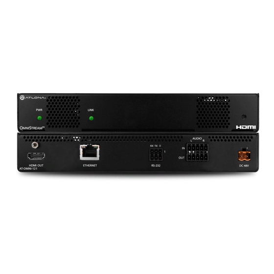
Page 9: Panel Description
Panel Description AT-OMNI-121 LINK TREAM AUDIO RX TX HDMI OUT ETHERNET RS-232 DC 48V AT-OMNI-121 RS-232 This LED indicator is green when the unit is Use the included Phoenix terminal block to powered. connect an RS-232 device to this port. LINK AUDIO These LED indicators show the active input... -
Page 10: At-Omni-122
Panel Description AT-OMNI-122 LINK AT-OMNI-122 AUDIO RX TX Eth 1 HDMI OUT Eth 2 RS-232 DC 48V Eth 1 / Eth 2 This LED indicator is green when the unit is Connect Ethernet cables from these ports to the powered. Local Area Network (LAN). -
Page 11: Installation
Installation RS-232 Both the AT-OMNI-121 and AT-OMNI-122 both provide RS-232 over IP, allowing communication between an automation system and an RS-232 device. This step is optional. Note that different Phoenix connectors are provided with each product. 1. Use wire strippers to remove a portion of the cable jacket. 2. -
Page 12: Audio
Installation Audio Both the AT-OMNI-121 and AT-OMNI-122 provide the ability to embed analog audio on the output stream and output downmixed 2-channel PCM, using the included dual five-pin Phoenix block. Note that each product comes with different Phoenix connectors. This step is optional. AT-OMNI-121 •... -
Page 13: At-Omni-122
Installation AT-OMNI-122 Use the top 5 pins to connect audio input sources. Use the bottom five pins to connect to audio output devices. 1. Use wire strippers to remove a portion of the cable jacket. 2. Locate the included Phoenix block connectors. Press the orange tab, above the terminal, while inserting the exposed wire. -
Page 14: Connection Diagram
Installation Connection Diagram Display Display Control System AT-OMNI-122 CT OR D IO R S- N I- A T- R S- N ET H ER AT-OMNI-112 N I- A T- Blu Ray Player Laptop AT-OMNI-121 / AT-OMNI-122... -
Page 15: Configuration
By default, OmniStream products are set to DHCP mode, allowing a DHCP server (if present) to assign each encoder/decoder an IP address. Once an IP address has been assigned, the Atlona Management System (AMS) can be used to manage the product on the network. AMS will only be able to discover decoders if they are on the same VLAN. - Page 16 Configuration 5. Under the Domain View, locate the IP address for the decoder. Single-channel decoders will be labeled as OMNI-121. Dual-channel decoders will be labeled as OMNI-122. If no OmniStream devices are found, then make sure that both the decoder and the computer that is running AMS are on the same subnet.
-
Page 17: Configuring A Static Ip Address
Configuration e. Restart the mDNS listener by clicking Start > Add Device > Auto > Start mDNS Discovery. After the mDNS listener is enabled, click the OK button to dismiss the message box. g. The list of OmniStream devices should now be listed under the Domain View pane. Configuring a Static IP Address The following section is only required to set an decoder, currently in Auto IP mode, to a static IP address. - Page 18 Configuration 13. Under the Configuration Details tab, locate the Network info 14. Enter the required network information for the encoder in the IP Address, Subnet, and Gateway fields. 15. Click the Save button in the bottom-right corner, to apply the changes. 16.
-
Page 19: The Virtual Matrix
The Virtual Matrix Accessing the Virtual Matrix 1. Click the Global node, under the Domain View pane, within AMS. 2. Click the Virtual Matrix tab in the top portion of the screen. Virtual Matrix tab Display (sink) Decoder Cross Connection Legend Physical Interface Source... - Page 20 The Virtual Matrix The virtual matrix provides a visual diagram of each encoder and decoder that has been detected by AMS. Each physical interface, source input, and display (sink) output, are arranged as follows, within the virtual matrix. For the following, refer to Figure 1. •...
-
Page 21: Physical Interfaces & Cross Connections
The Virtual Matrix Physical Interfaces & Cross Connections The following example provides a better understanding of how physical interfaces and cross connections work together. Figure 3 shows a very simple setup: two displays are connected to a dual-channel decoder. Both Ethernet cables are connected from the decoder to the Local Area Network (LAN). -
Page 22: Creating Cross Connections
The Virtual Matrix Creating Cross Connections The term physical interface, refers to the Ethernet cable that is connected to each encoder/decoder. Once a cross connection is created, decoding process will automatically begin. To stop the decoding process, refer to Removing Cross Connections (page 24) for more information. - Page 23 The Virtual Matrix 3. Click the Create button to create the cross connection. 4. The following message box will be displayed. If the operation is successful, the dialog will state that a cross connections has been successfully created. The IP address in the message box is the decoder IP address. Decoder IP address 5.
-
Page 24: Removing Cross Connections
The Virtual Matrix Removing Cross Connections Deleting a cross connection terminates the connection between two physical interfaces. Once deleted, the currently assigned video/audio stream will no longer be able to pass between the encoder and decoder. 1. Right-click on the desired cross connection. Unless the desired cross connection is known, it will be necessary to right-click on the cross connection to display the available options. -
Page 25: Scrambling
The Virtual Matrix Scrambling OmniStream supports 128-bit Advanced Encryption Standard (AES) scrambling for both audio and video streams. Scrambling can be enabled or disabled through AMS and can be individual applied video, audio, or both, and can be enabled either before or after the decoding process is started. When scrambling is enabled, the scrambling key can be found under the HDMI Output tab on the decoder. -
Page 26: Configuring Redundant Streams
The Virtual Matrix Configuring Redundant Streams OmniStream decoders have the ability to identify damaged or missing streams and will recover the image almost instantaneously. The decoder can access the same stream from two separate multicast addresses and switch between them, when necessary. 1. -
Page 27: The Ams Interface
The AMS Interface System Info tab The System Info tab provides general information about the decoder. The decoder has an identical interface. None of the fields under the System Info tab can be edited. Firmware Version Displays the current version of firmware. Model The model of the unit. - Page 28 The Debug button places the decoder in debug mode. WARNING: The Debug button is specifically designed for providing system-level troubleshooting information. Do not use this feature unless directed by an experience field technician or an Atlona Technical Support Engineer. IDENTIFY Click the Identify button to identify the physical unit on a network.
-
Page 29: Sap Tab
The AMS Interface SAP tab The SAP tab enables or disables the Session Announcement Protocol protocol. Enabling SAP configures the decoder to look for SAP messages from encoders on the network that are configured to send SAP. Any messages that are discovered will be displayed here. Enabled Click this box to enable SAP and tell the decoder to listen for SAP messages. -
Page 30: Ip Input Tab
The AMS Interface IP Input tab The IP Input tab provides configuration of each input, the assigned multicast address(es), and ports. Name The name used by AMS to identify the IP input. Enable Click this check box to enable the IP input. Interface Select the physical interface, that will be used to carry the multicast traffic, from this drop-down list. - Page 31 The AMS Interface Addresses Enter the IPv4 address of the encoder(s) in this field and is used as the SSM include/exclude list. Use the comma delimiter to separate multiple IP addresses. When using non-SSM networks, this field is ignored. Port Enter the mulitcast UDP listening port in this field.
-
Page 32: Serial Tab
The AMS Interface Serial tab The Serial Config tab provides serial port configuration when using control signals. Name The name used by AMS to identify the physical interface receiving the serial data. Baudrate Click this drop-down list to select the desired baud rate. Data Click this drop-down list to select the number of data bits. - Page 33 The AMS Interface Name The name used by AMS to identify the serial port. Port Click this drop-down list to select the serial port to use. Select the Not Used option to leave the serial port unassigned. Mode Click this drop-down list to select the serial mode. Mode Description Displays the command-line interface of the decoder.
-
Page 34: Hdmi Output Tab
The AMS Interface HDMI Output tab The HDMI Output tab provides options to configure the ouput streams. Name The name used by AMS to identify the HDMI output. Enable Click this checkbox to enable descrambling. Enter the scrambling key in this field. The scrambling key must be ASCII and must contain a minimum of eight characters. - Page 35 The AMS Interface Backup Input Select the secondary video backup IP input from this drop-down list. If the primary IP input is down, then the decoder will automatically switch to this input. Refer to the Backup Mode option, on the previous page, for setting the conditions for switching inputs.
- Page 36 The AMS Interface Input Click this drop-down list to select the primary audio IP input. Select the Not Used option to leave the audio input unassigned. Backup Mode Click this drop-down list to select the backup mode. Mode Description Backup source is disabled; join request not sent. Join Active The decoder sends a join request only when the decoder decides to switch between audio sources.
- Page 37 The AMS Interface Analog Input If Analog Input is connected, then click this check box to enable this option. Analog Power When the decoder is connected to the optional external 48V DC power supply, clicking this check box will turn the Analog Power to green.
-
Page 38: Logo Tab
The AMS Interface Logo tab The Logo tab provides the ability to upload a custom logo. This logo will be displayed when no video signal is detected. When using dual-channel decoders, separate logos can be uploaded: one for each channel. Upload Logo Click this button to upload the logo file. -
Page 39: Alarms Tab
The AMS Interface Alarms tab The Alarms tab provides a list of all alarms and warnings that have been detected. If no alarms or warnings are active, then the page will display No alarms. A list of alarms, warnings, and their descriptions are in the table, below. -
Page 40: Audio I/F
The AMS Interface Audio I/F Message Description HDMI1 no audio No audio signal is present HDMI2 no audio No audio signal is present No volume control Displayed when volume is increased while unit is in Mute mode unit is on mute IP Protocol Message Description... -
Page 41: Network Info Tab
The AMS Interface Network Info tab The Network Info tab provides the ability to enable or disable DHCP mode for each video channel. When DHCP mode is disabled, the IP address, subnet mask, and gateway must be provided. If using the dual-channel version, then the information on both Network 1 and Network 2 are provided. -
Page 42: Users Tab
The AMS Interface Users tab The Users tab provides the ability to manage user access rights. Two access levels are available: admin and operator. Creating users requires Administrator access. Username The name of the assigned user. Role Select one of the following options from this drop-down list. User Description Administrator... -
Page 43: License Tab
The AMS Interface License tab The License tab is used to install licenses on OmniStream products. For OmniStream v1.0.0, all available licenses are pre-installed on units at the factory. License Key Enter the license number in this field. Install License Click this button to install the license, once the license key has been entered. -
Page 44: Appendix
Appendix FEC Details Matrix Size, Overhead, and Latency • FEC can only work if a single packets from each row/column are missing. Multiple packets missing from each row/column will cause FEC to fail. • Due to the above, a smaller matrix is more robust, as there is a better chance of errors not occurring in the same row/column. -
Page 45: Fec, Latency, And Lip Sync
In order for FEC to work, the matrix must be filled in order to calculate the FEC packets. This introduces some additional latency. Due to high bitrates, this is not noticeable for video, but can be very significant for audio. Therefore, Atlona recommends either leaving FEC disabled for audio or using a very small matrix. •... -
Page 46: Mounting Instructions
Appendix Mounting Instructions OmniStream decoders includes two mounting brackets 6. Mount the unit using the oval-shaped holes, on each and four mounting screws, which can be used to attach rack ear. If using a drywall surface, a #6 drywall the unit to any flat surface. screw is recommended. -
Page 47: Rack Tray For Omnistream
OmniStream encoders/decoders in a convenient 1U rack tray. The OmniStream rack tray can be purchased directly from Atlona. 1. Position the OmniStream products, as shown in the illustration below. -
Page 48: Specifications
Appendix Specifications Video HD/SD 4096x2160@24Hz, 3840x2160@24/25/30Hz (UHD), 1080p@23.98/24/25/29.97/30 /50/59.94/60Hz, 1080i@25/29.97/30Hz, 720p@30/50/59.94/60Hz VESA* 1920x1200, 1680x1050, 1600x1200, 1600x900, 1440x900, 1400x1050, 1366x768, 1360x768, 1280x1024, 1280x800, 1280x768, 1152x768, 1024x768 Color Space YUV, RGB Codec VC-2 Chroma Subsampling 4:4:4, 4:2:2 Color Depth 8-bit, 10-bit, 12-bit Scaling Audio HDMI... - Page 49 Appendix RS-232 Baud Rate 2400 to 115200 bp/s Connector Molex, 3-pin x 2 Temperature Fahrenheit Celsius Operating 32 to 122 0 to 50 Storage -4 to 140 -20 to 60 Humidity (RH) 20% to 90% (non-condensing) Power Consumption ~13 W (w/o analog audio), TBD (w/ analog audio) Supply (optional) Input: 85 V ~ 264 V AC 50/60 Hz Output: 48 V DC, 0.83 A...
- Page 50 • 408.962.0515 • 877.536.3976 © 2017 Atlona Inc. All rights reserved. “Atlona” and the Atlona logo are registered trademarks of Atlona Inc. All other brand names and trademarks or registered trademarks are the property of their respective owners. Pricing, specifications and availability...
Need help?
Do you have a question about the OmniStream AT-OMNI-122 and is the answer not in the manual?
Questions and answers