
Related Manuals for Atlona AT-OMNI-512


Summary of Contents for Atlona AT-OMNI-512
- Page 1 OmniStream R-Type ™ Dual-Channel Networked AV Encoder Atlona Manuals AT-OMNI-512 Networked AV...
- Page 2 Version Information Version Release Date Notes 4/17 Initial release 7/18 Includes updates to 1.2.1 firmware AT-OMNI-512...
- Page 3 Welcome to Atlona! Thank you for purchasing this Atlona product. We hope you enjoy it and will take a extra few moments to register your new purchase. Registration only takes a few minutes and protects this product against theft or loss. In addition, you will receive notifications of product updates and firmware.
- Page 4 Atlona requires that products returned are properly packed, preferably in the original carton, for shipping. Cartons not bearing a return authorization or case number will be refused. Atlona, at its sole discretion, reserves the right to reject any products received without advanced authorization. Authorizations can be requested by calling 1-877-536-3976 (US toll free) or 1-408- 962-0515 (US/international) or via Atlona’s website at www.atlona.com.
- Page 5 Damage, deterioration or malfunction resulting from the installation or removal of this product from any installation, any unauthorized tampering with this product, any repairs attempted by anyone unauthorized by Atlona to make such repairs, or any other cause which does not relate directly to a defect in materials and/or workmanship of this product.
- Page 6 Where shielded interface cables have been provided with the product or specified additional components or accessories elsewhere defined to be used with the installation of the product, they must be used in order to ensure compliance with FCC regulations. AT-OMNI-512...
-
Page 7: Table Of Contents
Slate / Logo Insertion Deleting Slates / Logos Text Insertion The AMS Interface Device Info tab Input tab Input Video Generator Encoding tab Encoder Serial tab Serial Port Serial Configuration Command Session tab Video Audio Text tab Color Size Logo tab AT-OMNI-512... - Page 8 Table of Contents PTP tab Network tab The Virtual Matrix Layout and Operation Appendix Updating the Firmware Mounting Instructions Rack Tray for OmniStream Specifications AT-OMNI-512...
-
Page 9: Introduction
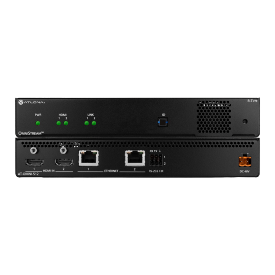
Introduction The Atlona OmniStream™ R-Type (AT-OMNI-512) is a networked AV encoder with two independent channels of encoding for two HDMI sources up to UHD @ 60 Hz and HDR, plus embedded audio and RS-232 or IR control pass- through. It is part of the OmniStream R-Type Series, designed for high performance, flexible distribution of AV over Gigabit Ethernet in residential and light commercial applications. -
Page 10: Panel Description
Connect the optional 48V DC power supply to information. this receptacle. This power supply is available, separately, and can be purchased through Atlona. Reboot button Press this button, using a small, pointed object to reboot the unit. AT-OMNI-512... -
Page 11: Installation
Installation RS-232 Connections The AT-OMNI-512 provides RS-232 over IP which allows communication between an automation system and an RS- 232 device. This step is optional. Either the top three or bottom three set of terminals can be used for RS-232. -
Page 12: Ir Connections
Unit GND (black) SIGNAL (white/black) TX out The following components are required. Note that other components may also be used. However, Atlona has tested and verified the following components for this application: • Xantech CB12 1 Zone Connecting Block •... - Page 13 Unicast Mode (page 25) Multicast Mode (page 27) for more information. AT-OMNI-IR-TX SIGNAL GROUND RX TX HDMI IN ETHERNET RS-232 / IR DC 48V AT-OMNI-512 Ethernet RX TX HDMI OUT ETHERNET RS-232 / IR AT-OMNI-521 SIGNAL GROUND RCVR 12 V DC SIGNAL...
-
Page 14: Connection Instructions
Connect the IR extender from the RX and GND pins of the RS-232 2 port to the associated pins on the control system. 5. Once power is applied, the PWR indicator, on the front panel, will turn red, then amber, then green. HDMI LINK TREAM PWR indicator RX TX HDMI IN ETHERNET RS-232 / IR DC 48V AT-OMNI-512 AT-OMNI-512... -
Page 15: Connection Diagram
Installation Connection Diagram Blu-ray Player Automation Control System CT OR RE SE 48 V M NI AT-OMNI-512 Projector AT-OMNI-521 M NI AT-OMNI-512... -
Page 16: Configuration
AMS is free and can be downloaded from https://www.atlona.com/ams. By default, the AT-OMNI-512 is set to DHCP mode, allowing a DHCP server (if present) to assign the encoder an IP address. Once an IP address has been assigned, the Atlona Management System (AMS) can be used to manage the product on the network. - Page 17 If no AT-OMNI-512 encoders are found, then verify the following: • The computer that is running AMS must be on the same network as the AT-OMNI-512. • Remove any network restrictions that may be in place. In order for mDNS to function properly, there must not be restrictions applied to the network.
- Page 18 Configuration 8. Click the desired AT-OMNI-521 from the Unassigned device list. Once the unit is selected, the control interface for the AT-OMNI-512 will be displayed. AT-OMNI-512...
-
Page 19: Configuring A Static Ip Address
Configuring a Static IP Address The following section is only required to set the AT-OMNI-512 encoder, currently in Auto IP mode, to a static IP address. If a DHCP server is not found within 60 seconds, encoders are automatically placed in Auto IP mode and will be assigned an IP address within the range 169.254.xxx.xxx. -
Page 20: Manual Setup
If no cable is connected, then the indicator will be red. Note that this indicator may also reflect the integrity of the cable: if the cable is bad or does not maintain a secure connection, then the Cable Present indicator may also be displayed as red. AT-OMNI-512... -
Page 21: Input Selection
4. Repeat the above steps for the Encoder 2 section. If a secondary HDMI source is not connected, then these fields may be left at their current settings. 5. Click the Save button, near the bottom of the page, to save all changes. AT-OMNI-512... -
Page 22: Session Configuration
Once the inputs have been assigned to the desired source, the next step is to configure each session. A session is a multicast IP address that is assigned to an AV stream. The AT-OMNI-512 supports up to four sessions (two sessions per Ethernet cable). -
Page 23: Basic Operation
PoE, the PWR indicator will be green. • Check the Ethernet cable for possible damage or loose connections. • Connect the optional 48V DC power supply (available from atlona. com) to the encoder. When using an external power supply, the PWR indicator will be red. •... -
Page 24: Id Button
HDMI IN RS-232 / IR ETHERNET DC 48V AT-OMNI-512 Reset to Factory-Default Settings. 1. Press and hold the ID button for approximately 30 seconds. 2. The LED indicators on the front panel will flash, then turn “off.” 3. The encoder is now reset and will need to be reconfigured. -
Page 25: Unicast Mode
3. Enter the IP address of the decoder in the Destination IP Address field. Repeat this process for each session. IP address of decoder 4. Scroll down to the bottom of the page and click the SAVE button to commit all changes. AT-OMNI-512... - Page 26 7. Remove the IP address from the Multicast Address field. 8. Click the SAVE button to commit changes. Field should be blank 9. Unicast setup is complete. The decoder unit will now receive streams exclusively from the encoder containing the IP address of this decoder. AT-OMNI-512...
-
Page 27: Multicast Mode
6. Create a cross-connection to the desired decoder. When a cross-connection is created, AMS will automatically assign a multicast IP address to both the encoder and decoder. By default, AMS automatically assigns a multicast IP address to each OmniStream encoder and decoder. Refer to the illustration on the following page, if necessary. AT-OMNI-512... - Page 28 Basic Operation AT-OMNI-512...
-
Page 29: Aes67 Audio
5. Click SESSION in the menu bar. 6. Scroll down to the Audio section and click the Enable AES67 toggle switch to enable or disable this feature. When enabled, the toggle switch will be green. Enable AES67 toggle switch (Session 1) AT-OMNI-512... - Page 30 Enable toggle switch and enable SAP. When enabled, the toggle switch will be green. Refer to the OmniStream R-Type A/V Decoder User Manual, if necessary. If the decoder is to receive AES67 audio, this step is required. 10. Click the SAVE button on the SAP page. AT-OMNI-512...
-
Page 31: Ir Control
8. Click the Bidirectional toggle switch to enable bidirectional control. Enabling this feature will provide the option of connecting the IR receiver to either the encoder or decoder. When enabled, the toggle switch will be green. 9. Click the SAVE button to commit changes. AT-OMNI-512... - Page 32 11. Under the Serial Port 2 section, click the Mode drop-down list and select Infrared. NOTE: Some hardware versions of OmniStream do not support IR. If infrared is not an option, then the version of OmniStream hardware being used, does not support IR. Contact Atlona for obtaining another unit.
-
Page 33: Edid Management
4. Scroll down to the bottom of the list and select + Add Custom EDID. 5. Enter the name of the EDID in the EDID Name field. Spaces and special character are valid entries. Use a descriptive name for this field. AT-OMNI-512... - Page 34 1080P MCH 4K60 MCH 4K60 PCM MCH 460 LPCM 2CH 720P DD 720P 2CH * Dolby Atmos® is carried with either Dolby Digital Plus or Dolby True HD audio streams. † DTS:X is carried with DTS-HD MA audio streams. AT-OMNI-512...
-
Page 35: Scrambling
16), if necessary. 2. Click SESSION in the menu bar. 3. Under the desired Session, click the Scrambling toggle switch to enable it. Once enabled, the toggle switch will be green and the Key field will be displayed: Key field AT-OMNI-512... -
Page 36: Using The Virtual Matrix
2. Locate the desired encoder or decoder. Scrambling is handled on the encoder; descrambling is handled on the decoder. 3. Click the yellow key icon. The Scrambling dialog box will be displayed. If the key icon for a decoder is clicked, then the Descrambling dialog box will be displayed. Key icon AT-OMNI-512... - Page 37 Click the icon to generate a random key using AMS. Each time this icon is clicked, a new scrambling key will be generated. 6. Repeat the above process for each session. 7. Click the Save button to commit the changes. AT-OMNI-512...
-
Page 38: Slate / Logo Insertion
4. Enter the name of the image in the Name field. If a name is not specified, then the UPLOAD button will be disabled. 5. Click the UPLOAD button to upload the file. 6. A new logo box will be added with the name of the logo that was provided in Step 4. AT-OMNI-512... -
Page 39: Deleting Slates / Logos
2. Click the DELETE button for the desired logo box. If the DELETE button is disabled, do the following: a. Scroll down to the Logo Insertion boxes. b. Click the Select Logo drop-down list and select Not Used. c. Click the SAVE button. d. Refresh the page. e. Click the DELETE button to remove the logo. AT-OMNI-512... -
Page 40: Text Insertion
9. Specify the size of the text in the Width (%) and Height (%) fields. Each of these values is based on the horizontal and vertical resolution of the screen. 10. Click the SAVE button to apply all changes. AT-OMNI-512... -
Page 41: The Ams Interface
Displays the MAC address of the ETHERNET 1 and ETHERNET 2 ports, respectively. Firmware version The version of firmware that the unit is running. Always make sure the latest version of firmware is installed. Upgrade Firmware Click this button to display the firmware update dialog. AT-OMNI-512... - Page 42 The configuration file will be saved in .json format. The default file name will be: AT-OMNI-512_settings_[dd-mm- yyyy]_12_7.json. Choose File Click this button to select the desired configuration file to be uploaded to the AT-OMNI-512. Once the file is selected, click the IMPORT CONFIGURATION button to upload the file. IMPORT CONFIGURATION Loads the currently selected configuration file to the AT-OMNI-512.
-
Page 43: Input Tab
Damaged cables may also display a red indicator. EDID Click the drop-down list to select the desired EDID. Refer to the table on the next page for a list of available EDID selections. Refer to EDID Management (page 33) for more information. AT-OMNI-512... -
Page 44: Video Generator
Click this toggle switch to enable or disable the built-in video generator. If the toggle switch is green, then the video generator is enabled. Name The internal name of the video generator. This field is read-only and cannot be changed. Color Depth Click the drop-down list to select the color depth of the video signal. AT-OMNI-512... - Page 45 Click the drop-down list to select the chroma subsampling value of the video signal. Resolution Width Enter the horizontal resolution of the video signal in this field. Resolution Height Enter the vertical resolution of the video signal in this field. AT-OMNI-512...
-
Page 46: Encoding Tab
Click this drop-down list to enable slate mode or select available: 8-Bit, 10-Bit, and 12-Bit. the desired slate to be used. Refer to Slate / Logo Insertion (page 38) and more information. Subsampling This value is set to 4:2:0 and cannot be changed. AT-OMNI-512... -
Page 47: Serial Tab
The AMS Interface Serial tab The Serial tab provides the ability to select the input for each encoder channel. Serial Port Name The name used by AMS to identify the serial port. Supported Modes Lists the supported protocols. AT-OMNI-512... -
Page 48: Serial Configuration
Enter the hexadecimal representation of the command in this field. NOTE: When entering the command string, it is not required to enter the string under both the ASCII and HEX fields. The encoder requires that one field be completed. AT-OMNI-512... -
Page 49: Session Tab
This option is locked and cannot be changed. Click this switch to enable to disable the Session Announcement Protocol. When enabled, the toggle switch will be green. Scrambling Check this box to enable scrambling. Scrambling can also be enabled/disabled using the Virtual Matrix. AT-OMNI-512... -
Page 50: Video
Destination IP Address Enter the endpoint IP address in the Destination IP Address field. Destination UDP Port Enter the UDP port in the Destination UDP Port field. The TTL (Time-To-Live) duration is set to 255 seconds and cannot be changed. AT-OMNI-512... - Page 51 Click this toggle switch to enable or disable bidirectional serial control. When enabled, the toggle switch will be green. This option only works when the auxiliary data stream is in unicast mode. Listen Port Enter the listening port for the data channel in this field, when using bidirectional serial control. AT-OMNI-512...
-
Page 52: Text Tab
Enter the scrolling speed in this field. Values from -255 to 255 are valid. Negative numbers will scroll the text from left to right. Positive numbers will scroll text from right to left. Iterations Enter the number of iterations in the Iteration field. Set this field to 0 (zero) to set the number of iterations to infinity. AT-OMNI-512... -
Page 53: Color
Width (%), Height (%) Specify the size of the text in the Width (%) and Height (%) fields. Each of these values is based on the horizontal and vertical resolution of the screen. AT-OMNI-512... -
Page 54: Logo Tab
Click this button to select the logo file to be uploaded.Files must be in .png format and must not exceed 5 MB (5120000 bytes) in size. When an image file is uploaded, it will appear in the Logo drop-down list. UPLOAD Click this button to upload the logo file to the AT-OMNI-512. AT-OMNI-512... - Page 55 Enter the vertical position of the logo on the screen. Height Enter the horizontal resolution of the logo, in pixels. Width Enter the vertical resolution of the logo, in pixels. NOTE: Maximum logo resolution (both height and width) is 1/4 of the video resolution. AT-OMNI-512...
-
Page 56: Ptp Tab
If a new device is added to the network and the GM changes, a brief outage will be experienced while all connected devices synchronize with the new clock. Because of this, Atlona recommends that one unit gets manually defined as the GM and have both Priority 1 and Priority 2 fields be set to 1. -
Page 57: Network Tab
IP Address Displays the IP address used by the channel. This field can only be changed if Static mode is selected. Subnet Displays the subnet mask for the channel. This field can only be changed if Static mode is selected. AT-OMNI-512... -
Page 58: The Virtual Matrix
1. Login to AMS. Refer to Accessing Encoders in AMS (page 16), if necessary. 2. Click the icon, in the upper-left corner of the AMS Dashboard. 3. Click Virtual Matrix. 4. The OmniStream Virtual Matrix page will be displayed. AT-OMNI-512... -
Page 59: Layout And Operation
To remove a cross-connection, click on the desired circle icon with the check mark symbol. The square with the dots around it will be displayed indicating that the cross-connection has been removed. Decoder Cross-connection Encoder • To view the individual streams for video, audio, and data, click the icons on the upper-left corner of the screen. AT-OMNI-512... - Page 60 Audio stream Data stream IMPORTANT: R-Type and Pro compatibility: R-Type encoders (AT-OMNI-512) and decoders (AT- OMNI-521) operate in Video Mode, only. Pro encoders can be set to either Video Mode or PC Mode. Video Mode is incompatible with PC Mode. Therefore, in order for both R-Type and Pro encoders/decoders to work within a system, Pro encoders/decoders must be set to Video Mode.
-
Page 61: Appendix
Appendix Updating the Firmware Firmware updates are managed through the Atlona Management System (AMS) software. 1. Click DEVICE INFO in the menu bar. 2. Click the UPDATE FIRMWARE button to display the Firmware Update dialog. Drag firmware file here 3. Click and drag the firmware file to yellow box, to upload the firmware to the device. OmniStream firmware files use the .v2pup file extension. - Page 62 9. Click the “X” to close out the progress bar window, then click the CLOSE button to dismiss the Firmware Update message box. 10. The firmware update process is complete. 11. Clear the web browser cache and refresh the web page. The new firmware version will appear in the Firmware Version field, in the DEVICE INFO page. AT-OMNI-512...
-
Page 63: Mounting Instructions
Appendix Mounting Instructions The AT-OMNI-512 encoder includes two mounting 6. Mount the unit using the oval-shaped holes, on each brackets and four mounting screws, which can be used rack ear. If using a drywall surface, a #6 drywall to attach the unit to any flat surface. -
Page 64: Rack Tray For Omnistream
OmniStream encoders/decoders in a convenient 1U rack tray. The OmniStream rack tray can be purchased directly from Atlona. 1. Position the OmniStream products, as shown in the illustration below. -
Page 65: Specifications
(image will only be displayed when source signal is lost). Control RS-232 Device control and configuration; supports baud rates from 2400 to 115200 Bidirectional pass-through from control system to network Pass-through from control system to network Pass-through from network to control system AT-OMNI-512... - Page 66 Operating Humidity (RH) 20% to 95%, non-condensing Chassis Dimensions (H x W x D) 1.34 in x 8.19 in x 4.41 in 34 mm x 208 mm x 112 mm Weight 1.5 lbs / 0.7 kg Safety CE, RoHS, FCC AT-OMNI-512...
- Page 67 • 408.962.0515 • 877.536.3976 © 2018 Atlona Inc. All rights reserved. “Atlona” and the Atlona logo are registered trademarks of Atlona Inc. All other brand names and trademarks or registered trademarks are the property of their respective owners. Pricing, specifications and availability...
Need help?
Do you have a question about the AT-OMNI-512 and is the answer not in the manual?
Questions and answers