Sign In
Upload
Manuals
Brands
SICK Manuals
Accessories
LFP Inox
SICK LFP Inox Hygienic Level Sensor Manuals
Manuals and User Guides for SICK LFP Inox Hygienic Level Sensor. We have
2
SICK LFP Inox Hygienic Level Sensor manuals available for free PDF download: Operating Instructions Manual
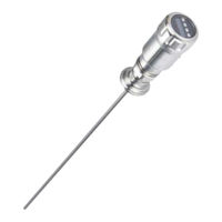
SICK LFP Inox Operating Instructions Manual (232 pages)
TDR level sensor
Brand:
SICK
| Category:
Accessories
| Size: 3 MB
Table of Contents
Deutsch
2
Table of Contents
2
1 LFP-Füllstandsensor
4
Funktionsprinzip
4
Sicherheitshinweise
4
Einsatzbereiche
4
Einbaubedingungen
5
Elektrischer Anschluss
7
Display
7
Montage Koaxialrohr
8
Sonde Kürzen
8
2 Inbetriebnahme des LFP
8
Kurzinbetriebnahme (mit Werkseinstellung)
8
Erweiterte Inbetriebnahme
9
Schauminbetriebnahme (mit Werkseinstellung)
10
3 Parametrierung der Schaltausgänge
12
Schalthysterese und Fensterfunktion
12
Schließer mit Einstellbarer Hysterese
13
Öffner mit Einstellbarer Hysterese
14
Schließer mit Fensterfunktion
15
Öffner mit Fensterfunktion
16
Schließer mit Fehlersignal
17
Öffner mit Fehlersignal
17
4 Parametrierung des Analogausgangs
18
Automatische Signalerkennung
18
Stromausgang 4-20 Ma
18
Spannungsausgang 0-10 V
18
5 Erweiterte Funktionen
19
Expert Modus
19
Messwerte Filtern
19
Testen der Parametrierung
19
Parametrierung der Sondenlänge
20
Statische Störsignale Einlernen
20
Signalqualität Auswerten
21
Koaxialkabellänge Editieren
22
Displayschutz Aktivieren
22
Anzeigeeinheit Auswählen (Millimeter/Inch)
22
Offset Einstellen
23
6 Menü-Übersicht
24
7 Fehlerbehebung
32
Fehlermeldung am Display
32
Bedienung am Display
33
Ausgänge
34
Verhalten
34
8 IO-Link
36
9 Technische Daten
40
Merkmale
40
Performance
41
Referenzbedingungen
41
Messgenauigkeit
42
Mechanik/Werkstoffe
42
Elektrische Anschlusswerte
43
Umgebungsbedingungen
43
Maßzeichnungen
44
Werkseinstellung
46
10 Zubehör
47
11 Wartung
50
12 Rücksendung
50
13 Entsorgung
50
14 Mediumsliste
50
15 Notizen
57
English
58
LFP Level Sensor
60
Principle of Operation
60
Safety Notes
60
Fields of Application
60
Installation Conditions
61
Electrical Connection
62
Display
63
Mounting the Coaxial Tube
63
Shortening the Probe
64
Commissioning the LFP
64
Quick Commissioning (with Factory Settings)
64
Advanced Commissioning
64
Foam Commissioning (with Factory Settings)
66
Configuring The Switching Outputs
68
Normally Open with Adjustable Hysteresis
70
Normally Closed with Adjustable Hysteresis
70
Normally Open with Window Function
71
Normally Closed with Window Function
72
Normally Open with Error Signal
73
Normally Closed with Error Signal
73
Configuring The Analog Output
74
Automatic Signal Detection
74
Current Output 4-20 Ma
74
Voltage Output 0-10 V
74
Advanced Functions
75
Expert Mode
75
Filtering the Measured Values
75
Testing The Configuration
75
Configuring The Probe Length
76
Programming Static Interference Signals
76
Evaluating the Signal Quality
77
Configuring Coaxial Cable Length
78
Enabling Menu Protection
78
Selection the Displayed Units (Millimeter/Inch)
78
Setting an Offset
79
8014485/YNN0/2016-02-01 © SICK AG • Level Sensors • Germany • Subject to Change Without Notice
79
Menu Overview
80
Troubleshooting
88
Error Message on the Display
88
Operating the Display
89
Outputs
90
Behavior
90
IO-Link
92
Technical Data
97
Features
97
Performance
97
Reference Conditions
98
Measurement Accuracy
99
Mechanics/Materials
99
Electrical Connection Values
100
Environmental Conditions
100
Dimensional Drawings
101
Factory Settings
103
Accessories
104
Disposal
108
Maintenance
108
Medium List
108
Returns
108
Notes
115
Español
116
1 Sensor de Nivel LFP
118
Principio de Funcionamiento
118
Indicaciones de Seguridad
118
Ámbitos de Aplicación
118
Condiciones de Montaje
119
Conexión Eléctrica
121
Pantalla
121
Montaje del Tubo Coaxial
122
Acortar la Sonda
122
2 Puesta en Marcha del LFP
122
Puesta en Marcha Breve (con Ajuste de Fábrica)
122
Puesta en Marcha Ampliada
123
Puesta en Marcha con Espuma (con Ajuste de Fábrica)
124
3 Parametrización de las Salidas de Conmutación
126
Histéresis de Conmutación y Función Ventana
126
Contacto de Cierre con Histéresis Ajustable
127
Contacto de Apertura con Histéresis Ajustable
128
Contacto de Cierre con Función de Ventana
129
Contacto de Apertura con Función Ventana
130
Contacto de Cierre con Señal de Error
131
Contacto de Apertura con Señal de Error
131
4 Parametrización de la Salida Analógica
132
Detección Automática de Señales
132
Salida de Corriente 4-20 Ma
132
Salida de Tensión 0-10 V
132
5 Funciones Ampliadas
133
Modo Experto
133
Filtrar Valores de Medida
133
Comprobación de la Parametrización
133
Parametrización Longitud de la Sonda
134
Programar Señales de Interferencia Estáticas (Parásitos)
134
Evaluación Calidad de la Señal
135
Configuración Longitud Del Cable Coaxial
136
Activar Protección de Pantalla
136
Seleccionar Unidad de Visualización (Milímetros/Pulgadas)
137
Ajustar el Offset
137
6 Vista en Conjunto del Menú
138
7 Resolución de Fallos
146
Aviso de Error en la Pantalla
146
Manejo en la Pantalla
147
Salidas
148
Comportamiento
148
8 IO-Link
150
9 Datos Técnicos
154
Características
154
Rendimiento
155
Condiciones de Referencia
155
Exactitud de la Medida
156
Mecánica/Materiales
156
Valores de Conexión Eléctrica
157
Condiciones Ambientales
157
Dibujos Acotados
158
Ajuste de Fábrica
160
10 Accesorios
161
11 Mantenimiento
165
12 Devolución
165
13 Eliminación
165
14 Lista de Sustancias
165
15 Notas
173
Français
174
1 Capteur de Niveau LFP
176
Principe de Fonctionnement
176
Consignes de Sécurité
176
Domaines D'application
176
Conditions de Montage
177
Raccordement Électrique
179
Écran
179
Montage du Tube Coaxial
180
Raccourcir la Sonde
180
2 Mise en Service du LFP
180
Mise en Service Rapide (Avec Réglage D'usine)
180
Mise en Service Avancée
181
Mise en Service Avec de la Mousse (Réglage D'usine)
182
Configuration Des Sorties De Commutation
184
Hystérésis de Commutation Et Fonction Fenêtre
184
Contact no Avec Hystérésis Réglable
185
Contact NF Avec Hystérésis Réglable
186
Contact no Avec Fonction Fenêtre
187
Contact NF Avec Fonction Fenêtre
188
Contact no Avec Signal D'erreur
189
Contact NF Avec Signal D'erreur
189
Configurer La Sortie Analogique
189
Détection Automatique de Signal
189
Sortie de Courant 4-20 Ma
190
Sortie de Tension 0-10 V
190
5 Fonctions Avancées
191
Mode Expert
191
Filtrage des Mesures
191
Test De La Configuration
191
Configuration De La Longueur De La Sonde
192
Fonction D'apprentissage des Signaux Parasites Statiques
193
Évaluation de la Qualité du Signal
193
Édition de la Longueur du Câble Coaxial
194
Activation de la Protection de L'écran
194
Sélection De L'unité Affichée (Millimètre/Inch)
195
Réglage de L'offset
195
6 Présentation des Menus
196
7 Suppression des Défauts
204
Message D'erreur À L'écran
204
Utilisation À L'écran
205
Sorties
206
Comportement
206
8 IO-Link
208
9 Caractéristiques Techniques
212
Caractéristiques
212
Performance
213
Conditions de Référence
213
Exactitude de Mesure
214
Système Mécanique/Matériaux
214
Valeurs des Raccordements Électriques
215
Conditions Ambiantes
215
Plans Cotés
216
Réglage D'usine
218
10 Accessoires
219
11 Maintenance
223
12 Retour
223
13 Mise Au Rebut
223
Liste Des Fluides
223
15 Notes
230
Advertisement
SICK LFP Inox Operating Instructions Manual (68 pages)
TDR Level Sensor
Brand:
SICK
| Category:
Accessories
| Size: 2 MB
Table of Contents
Table of Contents
3
1 About this Document
6
Information on the Operating Instructions
6
Scope
6
Explanation of Symbols
6
Further Information
7
Customer Service
7
2 Safety Information
8
Intended Use
8
Incorrect Use
8
Limitation of Liability
8
Modifications and Conversions
8
Requirements for Skilled Persons and Operating Personnel
9
Operational Safety and Particular Hazards
9
General Safety Notes
10
Repairs
10
3 Product Description
11
Product ID
11
Information on the Housing
11
Type Code
11
Product Characteristics
12
Device View
12
Operating Buttons
12
Product Features and Functions
13
Principle of Operation
13
Fields of Application
13
4 Transport and Storage
14
Transport
14
Transport Inspection
14
Storage
14
5 Mounting
15
Installation Conditions
15
Installation in a Container
15
Installation in a Metal Immersion Tube or Metal Bypass
16
Mounting the Coaxial Tube
17
Shortening the Probe
17
Procedure
17
6 Electrical Installation
18
Safety
18
Notes on the Electrical Installation
18
Electrical Connection
19
Overview of the Electrical Connections
19
Pin Assignment, M12 Plug Connector, 5-Pin
19
Pin Assignment, M12 Plug Connector, 8-Pin
20
Pin Assignment, Cable Variant, 5-Pin
20
Pin Assignment, Cable Variant, 8-Pin
20
7 Commissioning
21
Quick Commissioning (with Factory Settings)
21
Advanced Commissioning
21
Foam Commissioning (with Factory Settings)
23
8 Operation
25
Display and Pushbuttons
25
Variants with Two Switching Outputs
25
Variants with Four Switching Outputs
25
IO-Link
25
Configuring the Switching Outputs
26
Switching Hysteresis and Window Function
26
Normally Open with Configurable Hysteresis
27
Normally Closed with Configurable Hysteresis
28
Normally Open with Window Function
29
Normally Closed with Window Function
30
Normally Open with Error Signal
31
Normally Closed with Error Signal
31
Configuring the Analog Output
32
Automatic Signal Detection
32
Current Output 4 Ma
32
Voltage Output 0 V
32
Advanced Functions
33
Expert Mode
33
Filtering Measured Values
33
Automatic Interference Signal Limit Adjustment
34
Blanking Interference Signals in Masked Zone
34
Selecting Evaluation Process
35
Testing the Configuration
35
Configuring the Probe Length
36
Teaching in Static Interference Signals
37
Evaluating Signal Quality
37
Changing the Coaxial Cable Length
38
Activating the Display Lock
39
Selecting the Display Unit (Millimeter / Inch)
39
Setting the Offset
40
Resetting the Calibration
41
9 Menu Overview
42
10 Overview of Parameters
45
11 Troubleshooting
49
Error Message on the Display
49
Operating the Display
50
Outputs
51
Error Behavior
51
12 Repair
52
Maintenance
52
Returns
52
13 Disposal
53
14 Technical Data
54
Features
54
Performance
54
Mechanical/Materials
55
Reference Conditions
55
Ambient Conditions
55
Electrical Connections
56
Measurement Accuracy
57
15 Dimensional Drawings
58
16 Factory Setting
60
17 Accessories
61
18 Medium List
62
Advertisement
Related Products
SICK LFV 200
SICK LFV 330
SICK LFR
SICK LFC
SICK LMS511-20100 PRO Outdoor
SICK LMS511-22100 Heavy Duty Outdoor
SICK LMS531-11100 Lite Security Outdoor
SICK LiDAR
SICK LBV 321 NAMUR
SICK LBR
SICK Categories
Accessories
Security Sensors
Measuring Instruments
Scanner
Barcode Reader
More SICK Manuals
Login
Sign In
OR
Sign in with Facebook
Sign in with Google
Upload manual
Upload from disk
Upload from URL