Amroad ID5101 Quick Installation Manual
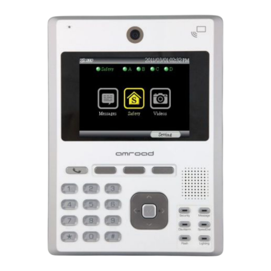
Video indoor station
Hide thumbs
Also See for ID5101:
- User manual (36 pages) ,
- User manual (91 pages) ,
- Installation manual (20 pages)
Advertisement
Quick Links
Package Contents
These items are included in your Video Indoor Station package. Check this list before
installation to ensure that you have received all items.
1. Video Indoor Station
2. Back Plate
3. Wall mounted screw pack
4. Screw Pack (2 pieces)
5. Screw for Earth Wire
6. H-type Terminal Connector for
Power Wire (1 pieces)
7. Main RFID Card
8. CD-ROM (containing Manual,
QIG, QOG, and Search Tool)
9. I/O Cable (3 pieces)
10. Relay Board (2 pieces)
11. Quick Installation Guide &
Quick Operation Guide
Please contact your dealer immediately if any item(s) is missing.
Rear Panel & GPIO Connectors
NOTE: To avoid electrical shock, we strongly suggest that connecting DC power to
ID5101 after ID5101 has installed on the wall.
Installing Video Indoor Station
Due to the view angle of the camera is limited, therefore the installation position for
Video Indoor Station is crucial. In order to get a better view, the view angle of this door
phone should be around 105. Also the height of the lens position is suggested at the
height of 155 cm according to building conditions.
Please reserve the space for junction wiring in the wall, you may refer to the embedded box
dimension as diagram below.
800-0000007-00-00
Installing Procedures
1. Screw the Back Plate on the wall.
Please pull out the DC wires and Ethernet cable pass through the back plate. Then,
connect them with the Video Indoor Station after securing the Back Plate on the wall.
If necessary, please connect the Earth wire to the screw as diagram below.
For more GPIO application, please refer to Safety/Security Application in next page
2. Connect the DC +12V wires and Ethernet cable.
Plug the DC wire connector of ID5101 to Power-Connecting connector, and connect
Ethernet cable to ID5101 as diagram below.
Be careful when you are connecting the DC wires, please check the power condition and
turn off the general power switch before you start to connect the wires.
3. Screw the Video Indoor Station with Back Plate.
Before connecting to Safety and Security Devices
GPIO connectors and I/O Pin Assignment and Wire Color
There are three GPIO connectors on the rear panel of your Video Indoor Station.
These GPIO connectors are used to connect with Safety and Security devices.
Before you begin to connect other devices to the ID5101, the I/O wires and their
colors for GPIO connectors are illustrated as pictures below.
GPIO connectors and I/O Pin Assignment and Wire Color
1
After connecting the wires and cables properly,
then screw the 2 screws that come with the
package into the front panel. Please double check
all the installation procedures again, then you may
power on the general power switch to start the
configuration procedures.
Advertisement

Related Manuals for Amroad ID5101


Summary of Contents for Amroad ID5101
- Page 1 These GPIO connectors are used to connect with Safety and Security devices. Before you begin to connect other devices to the ID5101, the I/O wires and their Due to the view angle of the camera is limited, therefore the installation position for colors for GPIO connectors are illustrated as pictures below.
- Page 2 IO Circuit and Application The ID5101, Video Indoor Station, provides 8 Input ports and 4 Output port for your house to set up Home Safety and Security; you may refer the following examples for each application. Please connect the adapter which comes with the package to the DC +12V as below and then connect your end devices according to your requirement.
- Page 3 CO Sensor, Emergency Button, Gas Detector, and Door Bell Button. There are two ways to configure ID5101. One is “Configure via Web UI”, the other is “Configure on ID5101”. Configure via Web UI This section describes how to configure your ID5101 with Web User Interface. This UI also provides remote management capability to service provider.
- Page 4 2. This setting password is different from Security password. Extra NOTE Network Setting NOTE 1: To open the door by pressing the “ # ” keypad on ID5101 Video Indoor Station, the door must have been installed “Electrical-door Lock”. This Network Setting allows you to set up the important parameters of NOTE 2: ID5101 RFID Internal Module, ISO 14443A Compliant/ 13.56 MHz RFID Mifare.
Need help?
Do you have a question about the ID5101 and is the answer not in the manual?
Questions and answers