Amroad DP101 User Manual
Video door phone
Hide thumbs
Also See for DP101:
- System integration manual (62 pages) ,
- Quick installation manual (2 pages)

Related Manuals for Amroad DP101


Summary of Contents for Amroad DP101
- Page 1 Video Door Phone User Guide VIDEO DOOR PHONE USER GUIDE Version: 1.00 Issued Date: 12/10/2009 For Models: DP101/DP101R/DP101RT/EP101/EP101T (Single Unit)
- Page 2 Contents Chapter 1 : Introduction Welcome General Application of Door Entry System Use of SIP Chapter 2 : Knowing Video Door Phone Package Contents Front Panel Rear Panel Dimensions Chapter 3 : Installing Video Door Phone Suggested Installation Positions Lighting Conditions Installing Procedures 1.
- Page 3 Video Door Phone User Guide SIP Services Entrance Settings – Extension Entrance Settings – GPIO Upgrade Configurations Chapter 5 : Using Video Door Phone Making Calls From Video Door Phone Answering Calls on IP Video Phone Open the Door (Optional function) Chapter 6 : Applications Functions Performed by the Devices...
-
Page 4: Introduction
Video Door Phone User Guide Chapter 1 : Introduction Welcome Thank you for choosing this Video Door Phone. This device is designed to co-work with IP Video Phone to compose a SIP based door entry system. Beside taking advantages of IP technologies, this system also can fully utilize the SIP protocol to link to your SIP VoIP services. -
Page 5: General Application Of Door Entry System
Video Door Phone User Guide General Application of Door Entry System There are two major models of Video Door Phone: DP101 series, single unit model. They are applied on different conditions. Please see following descriptions: Single Unit Application DP101 series is designed for units of apartment or single house. - Page 6 Video Door Phone User Guide Figure 2 : Community Application...
- Page 7 Video Door Phone User Guide Use of SIP SIP, initial of Session-Initiation-Protocol, it is an application-layer control (signaling) protocol for creating, modifying, and terminating sessions with one or more participants. These sessions include Internet telephone calls, multimedia distribution, and multimedia conferences.
-
Page 8: Knowing Video Door Phone
Video Door Phone User Guide Chapter 2 : Knowing Video Door Phone Package Contents The following items are included in your SIP camera package. Check this list before installation to ensure that you have received all items. 1. Front Panel 2. -
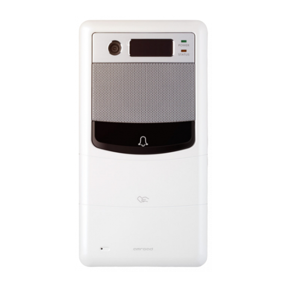
Page 9: Front Panel
Video Door Phone User Guide Front Panel Lens Module IR LED Speaker Door Bell Microphone Figure 5 : Front Panel... -
Page 10: Rear Panel
Video Door Phone User Guide Rear Panel Alarm Sensor Reset Button Ethernet RJ45 Connector Terminal Connector Pack 1 AC Cable of DP101 Figure 6 : Rear Panel and Connectors Figure 6 : Rear Panel and Connectors... -
Page 11: Dimensions
Video Door Phone User Guide Dimensions 40 mm 120 mm 230 mm Figure 7 : Dimensions... -
Page 12: Installing Video Door Phone
Video Door Phone User Guide Chapter 3 : Installing Video Door Phone Suggested Installation Positions Due to the view angle of the camera is limited, therefore the installation position for Video Door Phone is crucial. In order to get a better view, the view angle of this door phone should be around 85. -
Page 13: Installing Procedures
Video Door Phone User Guide Installing Procedures 1. Screw the Back Plate on the wall. Making a hole that is able to let the AC wires and Ethernet cable pass through .Hence to connect with the Door phone unit after screwing the Back Plate on the wall. -
Page 14: Connect The Ac Wires And Ethernet Cable
2. Connect the AC wires and Ethernet cable. Plug the AC cable connector of DP101 to Power-Connecting connector, and connect Ethernet cable to DP101 as Figure 10. Be careful when you are connecting the AC wires, please check the AC condition and turn off the general power switch before you start to connect the wires. -
Page 15: Screw The Video Door Phone With Back Plate
Video Door Phone User Guide 3. Screw the Video Door Phone with Back Plate. After connecting the wires and cables properly, then screw the 4 screws and water stopper that come with the package into the front panel. Please double check all the installation procedures again, then you may power on the general power switch to start the configuration procedures. -
Page 16: Configuring Video Door Phone
<Reset Function> The default IP type setting of Video Door Phone is “DHCP Client “. There is a reset button on the back of the DP101 1. Pressing the reset button for one second=>DP101 will turns to Fix IP mode as "192.168.0.50" and reboot by itself. -
Page 17: Entering Web User Interface
Video Door Phone User Guide Entering Web User Interface Input the IP address of this product on your browser, then you will see home page of the Video Door Phone like Figure 13. Web UI is protected by Login ID and Password. Press the “Login” button, then you will see 2 input fields: Login ID and Password. -
Page 18: System - Basic Settings
Video Door Phone User Guide System - Basic Settings Device ID – This ID is a unique number that assigned by manufacturer. Device Name – The field allows user to give a specified name for identification such as “Smith Family”. Date &... -
Page 19: System – Network Settings
Video Door Phone User Guide System – Network Settings MAC Address – This is a quasi-unique identifier attached to most network adapters. IP Type – You may select preferred IP type here. There are two options: DHCP Client and Fixed IP Address. The default value is DHCP Client. -
Page 20: System - Login Id
Video Door Phone User Guide System - Login ID You may change login ID and password of this Web UI here. There are 3 items: Login ID – Input new ID here. Password – Input new password here. Confirm Password – Input the new password again here to make sure the inputs are correct. -
Page 21: Phone Settings – Video
Video Door Phone User Guide Phone Settings – Video You may set change the video settings in this page. Bandwidth –You may select preferred bandwidth for video and audio streaming. There are 5 options: 128Kbps, 256Kbps, 384Kbps, 512Kbps and 768Kbps. Please check which bandwidth is suitable for you with your service provider. -
Page 22: Phone Settings – Audio
<IMPORTANT>: Please note, “turn on/off IR LED” and “adjust the brightness of CMOS” via Videophone prior to the “automatic CMOS Luma detection” function. DP101 can’t get the correct value of the CMOS brightness in some environment, please adjust the brightness value via the Videophone in conversation state, or turn on/off IR LED by yourself. - Page 23 Video Door Phone User Guide packet to the other end if this feature is enabled. CNG – You may enable or disable Comfortable-Noise-Generate function here. This phone will generate background noise when receiving silence packet from the other end if this feature is enabled. AEC Scene Setting –...
-
Page 24: Sip Services
Video Door Phone User Guide SIP Services You may setup advanced SIP service parameters in this page: Authentication Display Name – This name will show on the IP phone of called parties. You may fill in the preferred name here. ”Doorphone” is preferred. -
Page 25: Entrance Settings – Extension
Session Timer – You can set the session timer here. The range is from 0 to 1800 seconds. Default is 0 second. Media Timer – You can set the no continue media string timer here. The DP101 will discard the connection when the condition is happened. -
Page 26: Entrance Settings – Gpio
Service –You may enable or disable the function. Door Bell –The action of pressing the door bell on DP101 can be set as a trigger point. Trigger By Digit Input 3 – You can set the “Digit Input 3(DI3)” as a trigger point. You may select the voltage polarity “From High to Low”... - Page 27 Video Door Phone User Guide Function Name –You may fill out the function for memo. Trigger By Digit Input 1 – You can set the “Digit Input 1(DI1)” as a trigger point. You may select the voltage polarity “From High to Low”...
- Page 28 Master Card2 – The master card can issue new cards for the new Figure 24 : RFID residents. The Master Card2 can be issued by the Amroad’s software. Add User Function by Master Card – To allow the master card can issue new cards for the new residents.
-
Page 29: Upgrade
Video Door Phone User Guide Upgrade This section allows you to upgrade firmware of DP101 through network. There are 2 items in this page: Software Version - Shows current firmware version number. Select Target File - You may press “Browse” button to locate the new firmware that you wish to upgrade. -
Page 30: Configurations
Video Door Phone User Guide Configurations This section allows you to backup / restore the configure file. There are 2 items in this page: Export File – Backup the configure setting to your external storage. See Fig.24 Import File – Restore the configure setting from the backup file. See Fig.25. -
Page 31: Using Video Door Phone
Video Door Phone User Guide Chapter 5 : Using Video Door Phone Making Calls From Video Door Phone Using the Video Door Phone is quite simple. You will see “Door bell” on the front side . Press “Door Bell” to make a call. If there is no one answering this call, the bell sounds (Ding-Dong) will continuously ring until caller cancel this call by pressing again or the call will be disconnected automatically after 15 seconds. - Page 32 Video Door Phone User Guide DP101 RFID Card Usage Residents scan RFID card on the reader. DP101R will verify the database to determine whether drive the Digit Output 3. Issue RFID Master Card First Time Without any cabling, just scan RFID card on the DP101R reader when the DP101R device 1 time on-line.
-
Page 33: Applications
Video Door Phone User Guide Chapter 6 : Applications Functions Performed by the Devices Stolen prevention Web UI of reporting system set up -Able to set on/off this reporting function -When the reporting function is triggered, other external devices (Digit Output 4) can be triggered to call the police and notify the Videophone (Notice) as well Functional description -There are more than one way to receive the messages besides the alarm, for instance if the Notice connected to SIP or IP is... -
Page 34: Functions Performed By The Gpio Devices
Video Door Phone User Guide Functions Performed by the GPIO Devices Lighting condition Function Scene scenario − When the image is too dark on the videophone’s display due to the low light situationPlease refer the following steps: (1) IR LED module − Pressing “5”on Videophone to turn on the IR LED module, press again to turn it off. On the IR LED mode, the feature of the face can be recognized with black and white image (2) External lighting Source −... - Page 35 Video Door Phone User Guide Wiring set up To trigger SSR (Solid State Relay) with the internal power supply to turn on Burglar prevention Function Figure 28 : Auxiliary Light Wiring Scene scenario − Able to set on the setting (DI4) or set off the bugler alarm at home (1) Normal Close Various sensors are installed at home such as burglar prevention detected sensor (DI1/DI2 is connected with magnetic switches, glass vibration sensor, PIR …).
- Page 36 Video Door Phone User Guide Normal close situation can be use with the burglar prevention scenario Web UI of buglar prevention (DO2) - Able to turn on/off this function - When the function is triggered, Digit Output 2 will transmit the Polar Reverse - When the function is triggered other devices can be triggered (1) Ethernet...
- Page 37 Video Door Phone User Guide Figure 32 : Burglar Device Wiring Figure 31 : Burglar Device Wiring Controller Function Scene scenario − To provide a DO2 that can connect to the Digital input of other controller (e.g. Alarm or Door Access controller). Functional description −...
- Page 38 Video Door Phone User Guide Care Unit Function Scene scenario − The patient can ask the help from the nurses by pressing the door bell button in the care unit .While the meantime the DO4 will receive the turn on signal, if there is a external emergency light on the entrance of the unit in order to notify nurses around.
- Page 39 Video Door Phone User Guide Wiring set up Figure 34 : Emergency Button Wiring Figure 35 : External Alarm Wiring...
- Page 40 Hearing-Impaired Function Scene scenario When a visitor presses the door bell on the DP101, the corresponding pre-set video phone will start to ring and in the meantime the warning light will be turn on to notify the people having the hearting problem.
-
Page 41: Functions Performed By The Ip-Pbx
Video Door Phone User Guide Functions Performed by the IP-PBX Simultaneous Ring –The Distribution Policy is set to Ring All. e.g. When a visitor calls the group call (say extension 500), group members (say extensions 155, 157, and 166) will all ring simultaneously. Call Forwarding –... -
Page 42: Regulatory Information
Video Door Phone User Guide Appendix A : Regulatory Information FCC STATEMENT This product has been tested and complies with the specifications for a Class B digital device, pursuant to Part 15 of the FCC Rules. These limits are designed to provide reasonable protection against harmful interference in a residential installation. This equipment generates, uses, and can radiate radio frequency energy and, if not installed and used according to the instructions, may cause harmful interference to radio communications. -
Page 43: Ce Declaration Of Conformity (Europe)
Video Door Phone User Guide CE DECLARATION OF CONFORMITY (EUROPE) Manufacturer declares that this product conforms to the specifications listed below, following the provisions of the European R&TTE directive 1999/5/EC: EN 301 489-1, 301 489-17 General EMC requirements for Radio equipment. EN 609 50 Safety EN 300-328-1, EN 300-328-2 Technical requirements for Radio equipment.
Need help?
Do you have a question about the DP101 and is the answer not in the manual?
Questions and answers