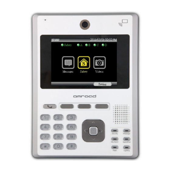
Amroad ID5101 Installation Manual
Home station
Hide thumbs
Also See for ID5101:
- User manual (36 pages) ,
- User manual (91 pages) ,
- Quick installation manual (4 pages)
Table of Contents
Advertisement
Quick Links
Advertisement
Table of Contents

Summary of Contents for Amroad ID5101
- Page 1 AMROAD ID5101 HOME STATION Installation Manual...
-
Page 3: Table Of Contents
AMROAD ID5101 Contents Contents Contents .......... i Package Contents ......1 The Size of Main Unit ...... 2 Rear Side ......... 3 Reset Button ..........3 Installing Procedures ...... 4 Back Plate ..........4 Wire and Cable Connection ..... 5 Install Main Unit ........ -
Page 4: Package Contents
AMROAD ID5101 Package Contents Package Contents Main Unit x1 Adapter x1 Back Plate x1 I/O Cable x3 Wall Mounted Screw Pack (Self Tapping Relay x2 Screw TP3-L16 x4, Wall Plug x4) RFID Master Card x1 Screw M4-L10 x2 Quick Installation Guide & Quick... -
Page 5: The Size Of Main Unit
AMROAD ID5101 The Size of Main Unit The Size of Main Unit... -
Page 6: Rear Side
AMROAD ID5101 Rear Side Rear Side Reset Button 1. The device will be switched to the static IP mode and reboot itself when the user has pressed the reset button for 3 seconds. 2. When the button has been pressed for... -
Page 7: Installing Procedures
AMROAD ID5101 Installing Procedures Back Plate Installing Procedures Back Plate Make sure that is able to let the Power Cord, Ethernet cable, and Earth Wire pass through the hole. The bottom of standard wall box is height 134cm from the floor. -
Page 8: Wire And Cable Connection
AMROAD ID5101 Installing Procedures Wire and Cable Connection Wire and Cable Connection Connect Ethernet Cable. (RJ-45 Connector). Connect the DC power cord of DP100 to H-type power connector. Please be careful to connect power cord DC +12V from wall. There are 8 input ports and 5 output ports on the rear side. -
Page 9: Install Main Unit
AMROAD ID5101 Installing Procedures Install Main Unit Install Main Unit After connecting the wires and cables properly, then screw the 2 screws (M4-L10) that come with the package into the front panel. Please double check all the installation procedures again, then you may power on the general power switch to start the configuration procedures. -
Page 10: Io Application
AMROAD ID5101 IO Application PIN Color and GPIO Connectors IO Application PIN Color and GPIO Connectors Before begin to connect other devices to the ID5101, the I/O cables and their colors for GPIO connectors are illustrated as figure above. -
Page 11: Lighting Control
AMROAD ID5101 IO Application Lighting Control Lighting Control The illustrations show how to use first GPIO connector and wire to connect Adapter and two Relay Boards for Lighting Control. -
Page 12: Alarm
AMROAD ID5101 IO Application Alarm Alarm The illustrations show you how to use first GPIO connector and wire to connect AC Power, Adapter and Relay Board for ALARM system. -
Page 13: Magnetic Switch
AMROAD ID5101 IO Application Magnetic Switch Magnetic Switch Both diagram and photo show how to use second row of the GPIO connector to connect with Magnetic Switches, and you can connect up to four magnetic switches accordingly based on the diagram or photo. -
Page 14: Co Sensor
AMROAD ID5101 IO Application CO Sensor CO Sensor Both diagram and photo show how to use 3rd GPIO connector to connect CO Sensor, and connect CO Sensor based on the diagram or photo. -
Page 15: Emergency Button
AMROAD ID5101 IO Application Emergency Button Emergency Button Both diagram and photo show how to use 3 GPIO connector to connect Emergency Button. The purple wire on the third-row GPIO connector is used to connect the NO wire. -
Page 16: Gas Detector
AMROAD ID5101 IO Application Gas Detector Gas Detector Both diagram and photo show how to use 3rd GPIO connector to connect Gas Detector. The gray wire on the third-row GPIO connector is used to connect the NO wire. Besides, Gas Detector needs to connect an external AC Power. - Page 20 AMROAD TECHNOLOGY INC. 17F.-1, No.16, Jian 8th Rd., Zhonghe Dist., New Taipei City 235, Taiwan (R.O.C.) 886-2-8226-5686 886-2-8226-5687 info@amroad.com.tw WWW.AMROAD.COM.TW...


Need help?
Do you have a question about the ID5101 and is the answer not in the manual?
Questions and answers