Table of Contents
Advertisement
Quick Links
Advertisement
Table of Contents

Related Manuals for Amroad XL COMMUNITY STATION


Summary of Contents for Amroad XL COMMUNITY STATION
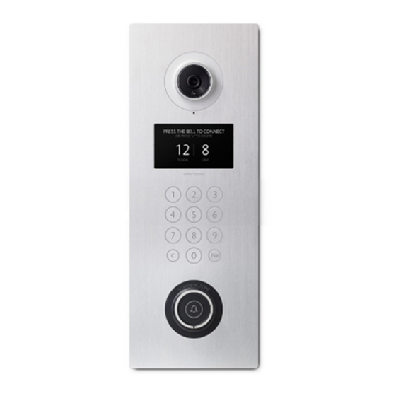
- Page 1 AMROAD XL COMMUNITY STATION Installation Manual...
-
Page 3: Table Of Contents
AMROAD XL Contents Contents Contents..........i Package Contents ....... 1 Rear Side ........... 2 Reset Button ..........2 Wire and Cable Connection ....3 Power cord and Ethernet ......3 GPIO & Relay Control ........3 Ground Wire ..........4 Install Main Unit .......... -
Page 4: Contents
AMROAD XL Package Contents Package Contents Main Unit x1 2-pin terminal block + cord end terminal x 2 (GRAY x1, BLUE x1) 5-pin Terminal block + 2-pin Terminal block + Cord End Terminal x7 (YELLOW Relay x1 Fixing Tool x1... -
Page 5: Rear Side
AMROAD XL Rear Side Rear Side Rear Cover After unfasten Rear Cover, IO connecter will 2. When the button has been pressed for show above. more than 6 seconds, the device will be Reset Button back to the factory setting and reboot itself. -
Page 6: Wire And Cable Connection
AMROAD XL Installing Procedures Wire and Cable Connection Wire and Cable Connection IO Connection: Power cord and Ethernet 1. DI1 (Digital Input port 1) :DI1 is used for Connect Power cord (DC12V) with 2-Pin detecting whether the door is closed or not. -
Page 7: Ground Wire
AMROAD XL Installing Procedures Wire and Cable Connection Ground Wire Connect the black wire (ground wire) to the wall box. Remember to tighten the screws on both sides. In order to prevent power surge and lighting strike from damaging the device, the wallbox should be connected to the earth wire of the building. -
Page 8: Install Main Unit
AMROAD XL Installing Procedures Install Main Unit 4. Push down Main Unit and secure it on the Confirm mounting box, power cord, wall. Ethernet and IO controllers are connected well. 2. Make sure “Slide Guide” and “Guide Rod” on the right position. Otherwise, they would not bump into “Iron Plate for Latch.”... -
Page 9: Use Fixing Tool To Lock
AMROAD XL Installing Procedures Use Fixing Tool to Lock Insert “Fixing Tool” into device and mounting box. 2. If move the “Fixing Tool” to the right side, Slide Latch will be moved to lock on the wall. 3. Remove the “Fixing Tool.”... -
Page 10: Io Application
AMROAD XL IO Application Electric Bolt IO Application Electric Bolt DI1:Trigger Default is HighLow, The Electric Bolt is closed when +12 V is supplied. MS(Magnetic Switch). Magnetic Switch is detecting door status. The Electric Bolt is opened when +12V is ... -
Page 11: Electric Strike
AMROAD XL IO Application Electric Strike Electric Strike DI1:Trigger Default is HighLow。 The Electric Strike is opened when +12 V is supplied. When the electronic circuit connected with the The Electric Strike is closed when +12V is Electric Strike completely, you should choose ... -
Page 12: Electric Lock With Open Door Button
AMROAD XL IO Application Electric Lock with Open Door Button Electric Lock with Open Door Button If all above steps are correct, you can press In addition to Electric Lock and Open Door Open Door Button to trigger the Electric Lock Button, we use wires, Relay Board, Core End (open door). - Page 13 AMROAD XL IO Application Electric Lock with Open Door Button...
- Page 16 AMROAD TECHNOLOGY INC. 17F.-1, No.16, Jian 8th Rd., Zhonghe Dist., New Taipei City 235, Taiwan (R.O.C.) 886-2-8226-5686 886-2-8226-5687 info@amroad.com.tw WWW.AMROAD.COM.TW...
Need help?
Do you have a question about the XL COMMUNITY STATION and is the answer not in the manual?
Questions and answers