Table of Contents
Advertisement
Quick Links
Download this manual
See also:
User Manual
Advertisement
Table of Contents

Related Manuals for Amroad DP101


Summary of Contents for Amroad DP101
- Page 2 DISCLAIMER Amroad reserves the right to change product specification without prior notice. Changes may be made to the information in this publication without obligation to notify. Amroad shall not be liable for technical or editorial errors contained herein. TRADE MARKS Amroad logo is copyright of Amroad Technology Inc.
-
Page 3: Table Of Contents
CONTENTS Contents ..................................................... OPYRIGHT .................................................... ONTENTS CHAPTER 1: INTRODUCTION ...............................................1 .....................................................1 ELCOME ........................................3 ENERAL PPLICATION OF NTRY YSTEM SIP ....................................................5 SE OF CHAPTER 2 : KNOWING VIDEO DOOR PHONE..........................................6 ................................................6 ACKAGE ONTENTS ..................................................7 RONT ANEL LED I ...................................................8 NDICATORS ..................................................10 ANEL ..................................................11 IMENSIONS... - Page 4 ..............................................18 YSTEM ASIC ETTINGS System – Network Settings ............................................20 System –Login Name..............................................21 System Reboot................................................21 Phone Settings – Audio .............................................24 SIP S ..................................................26 ERVICES – E ..........................................28 NTRANCE ETTINGS XTENSIONS – GPIO ..............................................33 NTRANCE ETTINGS – WIZARD ............................................35 NTRANCE ETTINGS –RFID (O )..........................................37 NTRANCE ETTINGS...
- Page 5 Electric Bolt................................................50 Electric Bolt with Open Button ..........................................51 Lighting condition Function............................................52 IP-PBX (C IP-PBX).................................54 UNCTIONS ERFORMED BY THE OMPATIBLE WITH MORAD FCC STATEMENT................................................55 CE DECLARATION OF CONFORMITY (EUROPE)....................................56...
-
Page 6: Contents
CONTENTS... -
Page 7: Chapter 1: Introduction
DP101/R MANUAL FOR SYSTEM INTEGRATOR Chapter 1: Introduction Welcome Thank you for choosing this Video Door Phone. This device is designed to co-work with IP Video Phone to compose a SIP based door entry system. Besides taking advantages of IP technologies, this system also can fully utilize the SIP protocol to link to your SIP VoIP services. - Page 8 DP101/R MANUAL FOR SYSTEM INTEGRATOR Friendly web user interface for configuration and management. Support PoE (Power over Ethernet, 802.3af) module (External power supply AC 48V) Please read this user guide before installing the device. Please contact your dealers or system integrators if you have questions.
-
Page 9: General Application Of Door Entry System
DP101/R MANUAL FOR SYSTEM INTEGRATOR General Application of Door Entry System There are two major series of Video Door Phone: community series and single unit series. They are applied on different conditions. Please see following descriptions: Single Unit Application Single unit series is designed for units of apartment or single house. - Page 10 DP101/R MANUAL FOR SYSTEM INTEGRATOR Community Application Community series is designed for building, apartment or community. Please see the diagram demonstrated with DP100 series. Connect each house or apartment with a large IP PBX. Tenants can check visitors, monitor public...
-
Page 11: Use Of Sip
DP101/R MANUAL FOR SYSTEM INTEGRATOR Use of SIP SIP, initial of Session-Initiation-Protocol, it is an application-layer control (signaling) protocol for creating, modifying, and terminating sessions with one or more participants. These sessions include Internet telephone calls, multimedia distribution, and multimedia conferences. -
Page 12: Chapter 2 : Knowing Video Door Phone
DP101/R MANUALR Chapter 2 : Knowing Video Door Phone Package Contents The following items are included in your Video Door Phone package. Check this list before installation to ensure that you have received all items. 1. Front Panel 2. Video Door Phone Unit 3. -
Page 13: Front Panel
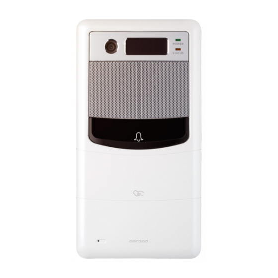
DP101/R MANUALR Front Panel Front Panel... -
Page 14: Led Indicators
DP101/R MANUALR LED Indicators There are two LED Indicators and Blue door bottom light which display status shown as below. Blue door bottom Green LED Orange LED Description (White LED) Twinkle Boot Up (I) (ON- 3 seconds; OFF- 1 seconds) - Page 15 DP101/R MANUAL ON- 3 seconds Scanning RFID card – Card is Rejected. Twinkle RFID hardware Fails ( It’s suggested that (ON- 1 second you should contact Service Center) OFF- 1 second) Twinkle twice “Security” is On. every 3 seconds Twinkle...
-
Page 16: Rear Panel
DP101/R MANUAL Rear Panel Figure 7: Rear Panel... -
Page 17: Dimensions
DP101/R MANUALR Dimensions Depth- 40 mm (1.57 inches) Width- 120 mm (4.72 inches) Height- 230 mm (9.06 inches) Figure 8: Dimensions... -
Page 18: Chapter 3 : Installing Video Door Phone
DP101/R MANUALR Chapter 3 : Installing Video Door Phone Suggested Installation Positions Due to the view angle of the camera is limited, therefore the installation position for Video Door Phone is crucial. In order to get a better view, the view angle of this door phone should be around 105 . -
Page 19: Installing Procedures
DP101/R MANUALR Installing Procedures 1. Screw the Back Plate on the wall. Making a hole that is able to let the AC wires and Ethernet cable pass through. Connect with the Video Door phone unit after screwing the Back Plate on the wall. If necessary, please connect the Earth wire to the screw as below. -
Page 20: Connect The Ac Wires And Ethernet Cable
2. Connect the AC wires and Ethernet cable. Plug the AC cable connector of DP101/R to the connector, and connect Ethernet cable to DP101/R as diagram below. Be careful when you are connecting the AC wires, please check the AC condition and turn off the general power switch before you start to connect the wires. -
Page 21: Screw The Video Door Phone With Back Plate
DP101/R MANUALR 3. Screw the Video Door Phone with Back Plate. After connecting the wires and cables properly, then screw the 4 screws and water stoppers that come with the package into the front panel, put back front cover. Please double check all installation procedures again, then you may power on the general power switch to start the configuration procedures. -
Page 22: Chapter 4 : Configuring Video Door Phone
DP101/R MANUAL Chapter 4 : Configuring Video Door Phone Finding Video Door Phone on Networks The default connection type setting of the Video Door Phone is “DHCP Client”, it is a typical network mode. There is a software utility provided by your local distributor or local dealer which is able to help you to find your Video Door Phone when using dynamic IP address. -
Page 23: Entering Web User Interface
2. There is a reset button on the back of the DP101/R A. Pressing the reset button for 3 seconds=>DP101/R will turn into Statics IP mode as "192.168.0.50" and reboot by itself. B. Or pressing for over 6 seconds =>Turn to DHCP mode as the default value and reboot by itself (Restore to factory setting). -
Page 24: System - Basic Settings
DP101/R MANUAL System - Basic Settings Item Description Device ID This ID is a unique number that assigned by manufacturer. Date & Time Here shows date and time set on this phone. Set New Time These fields allow user to set correct date and time and Date according to the local–standard. - Page 25 DP101/R MANUAL End time: Select ending time of lighting. NOTE: While setting Start Time and End Time, Start Time should be earlier than End Time. Language This feature allows you to select the language of audio announcement. Select “English” or “Traditional Chinese”...
-
Page 26: System - Network Settings
DP101/R MANUAL System – Network Settings Item Description MAC Address This is a quasi-unique identifier attached to most network adapters. IP Type The default value is DHCP Client. There are three options: DHCP Client, Static IP and PPPoE. A. DHCP Client: The system will automatically assign you an IP address. -
Page 27: System -Login Name
Figure17: System Login Name System Reboot When user needs to reboot DP101/R remotely, just click “Reboot” button on this webpage to start this action. After confirm rebooting, Web User Interface will back to the home page, but the video door phone may take 30~60 seconds to restart its system. - Page 28 DP101/R MANUAL Phone Settings – Video You may set change the video settings in this page. Item Description Bandwidth You may select preferred bandwidth for video and audio streaming. There are 4 options: 128Kbps, 256Kbps, 384Kbps, and 512Kbps. Please check which bandwidth is suitable for you with your service provider.
- Page 29 NOTE: “Turn on/off WL LED” and “adjust the brightness of CMOS” via Video Door Phone prior to the “automatic CMOS Luma detection” function. DP101/R can’t get the correct value of the CMOS brightness in some environment, please adjust the brightness value via the Video Door Phone by pressing “2”(brighter) or “8”(darker) in conversation state, or...
-
Page 30: Phone Settings - Audio
The voice intensity that is around normal intensity will be processed to be the value (-23db). (Acceptable value -20~-32) You may enable or disable Voice-Active-Detection function here. The DP101/R will detect background noise and send silence packet to the other end if this feature is enabled. This allows... - Page 31 DP101/R MANUAL You may enable or disable Comfortable-Noise-Generate function here. The DP101/R will generate background noise when receiving silence packet from the other end if this feature is enabled. This allows called parties hear better audio quality. Speaker This item allows you to select volume of speaker. There are 10 levels, 0 ~ 9.
-
Page 32: Sip Services
Account Password You may fill in the password of your SIP service account. For example, 812 SIP Proxy Server Service You may select “Enable” or “Disable” the SIP Proxy Server in the dropdown menu. NOTE: For Peer-to-Peer mode, both devices (DP101/R and remote device) need to select... - Page 33 NOTE: If none of the five White Lists is filled out, it means all phone number(s) can call in. ICMS8000 Input the IP address of ICMS8000. This function is customized and it allows DP101/R to send pictures of visitors to ICMS8000.
-
Page 34: Entrance Settings - Extensions
DP101/R MANUAL Entrance Settings – Extensions You may configure call services in this page: ITEM Description Called Party Fill in the extension number. When Door Bell Extension button is pressed, the device will dial to the Number called party extension number. (The extension number or group that is assigned by IP PBX.) - Page 35 You may enable or disable the function.(Disable/trigger always) Door Bell Button The action of pressing the door bell on DP101/R can be set as a trigger point. (This configuration is only for hospital environment.)(Disable/Enable) Trigger By Digit Input 3 You can set the “Digit Input 3(DI3)” as a trigger point. You may select the voltage polarity...
- Page 36 (specific application only). The call out number can be set in the “Entrance Settings – Extensions: Called Out Extension Number” field. Email Setting The e-mail content is the picture taken by DP101/R. There are three ways which may trigger e-mail function.
- Page 37 DP101/R MANUAL Trigger By DI1 You can enable/disable the “Digit Input 1(DI1)” as a trigger point for sending Email for notification. Trigger By RFID (10) You may enable or disable the sending Email function. The function is triggered when swipe /RFID RFID card 5 seconds continuously to alarm security system via DO3.
- Page 38 DP101/R MANUAL NOTE: Be careful with the wires connection of GPIO, especially the default polar voltage of hardware (digit output pins) is high. Please select and set the related electric circuit to meet the hardware initial voltage.
-
Page 39: Entrance Settings - Gpio
DP101/R MANUAL Entrance Settings – GPIO You may configure GPIO in this page: ITEM Description Auxiliary Digit If some external devices are connected to Output 2 the DO2 (Pin : Digit Output 2), you may enable or disable the voltage polarity changeable in the auxiliary DO2. - Page 40 DP101/R MANUAL Ethernet Some trusted Ethernets can be set up as a trigger point. Please contact with the provider when you need more information. Notice Number via You may fill in the extension number here, it will send SIP Messages to the extension when Message (SIP) the internal alarm is triggered.
-
Page 41: Entrance Settings - Wizard
Light)”, ” DO2 Function” and ” DO4 Function”. The WIZARD brief setting can cover almost of the “Extensions” and “GPIO” settings. ITEM Description Select Function With Video Door Phone (DP101/R) Wizard Performed by the configuration, the administrator can set GPIO Devices basic configurations for the GPIO of Video Door Phone easily. - Page 42 You can select “Care Unit Function”, “Emergency Button Case A”, “C Emergency Button Case B”. If you need above applications, please contact with Amroad. The following brief status can be shown. External Alarm connect with DO4) ...
-
Page 43: Entrance Settings -Rfid (Optional)
DP101/R MANUAL Entrance Settings –RFID (Optional) You may get the related RFID information and delete the issued RFID Cards here. ITEM Description Master Card1 This field will display the card number of the Master Card. By default, this field is null. - Page 44 DP101/R MANUAL card. The item Erase RFID Number will appear. Then, you may input the specific issued RFID card number to delete it.
-
Page 45: Upgrade - Firmware Update
DP101/R MANUAL Upgrade – Firmware Update The Upgrade function allows you to upgrade firmware of the DP101/R. The ways to upgrade the firmware are via Web UI. Item Description Hardware This field is to show firmware version number. Version Software... - Page 46 DP101/R MANUAL RFID Module This field displays the version of the RFID Module. (For DP101R Only) Version Restore Factory Press the Restore Default button and wait for system to restore its original factory default setting. Default...
-
Page 47: Configurations
Upload After selecting the configuration file, you can press Upload button to start the importing. Export File You can also use Export File to back up DP101/R Figure 27: Configuration settings on your computer. Download Press Download button to export, and you are prompted to click “Open” or “Save” for NewConfiguration.xml. -
Page 48: Ar Aps
This webpage allows manufacturing factory to perform management function through APS (Auto Provision Server). Figure 28: Auto Provision Server Item Description APS Server: This allows you to upgrade firmware of DP101/R through network. For example, APS Server: https://rc.amroad.com.tw/aps/TaServlet/doorphone.php Save Click this button to save your setting. -
Page 49: Chapter 5 : Using Video Door Phone
DP101/R MANUAL Chapter 5 : Using Video Door Phone Making Calls From Video Door Phone Using the Video Door Phone is quite simple. You will see “Door bell” on the front side. Press “ Door Bell ” button to make a call. -
Page 50: Common Controls
DP101/R MANUAL Common Controls You may press the “5” key of the IP Video Phone/Video Indoor Station to turn on/off the WL LED during answering the call. You may press the “2” or “8” key of the IP Video Phone/Video Indoor Station to adjust the CMOS brightness. -
Page 51: Dp101R Rfid Card Usage (Optional)
DP101/R MANUAL DP101R RFID Card Usage (Optional) Tenants scan RFID card on the reader. DP101R will verify the database to determine whether to open the door or not. Issue RFID Master Card First Time For the first time, after the installation of DP101R is completed, take the Master RFID Card from package contents to scan on the DP101R RFID reader. -
Page 52: Scanning Rfid Card To Open Door
DP101/R MANUAL Scanning RFID Card to Open Door While you are Scanning RFID Card on DP101R to Open Door… Scanning RFID Card Sound from the DP101R’s Speaker Result Card Accepted There will be the sound of “Bi! Bi!” from speaker…... -
Page 53: Chapter 6 : Applications
Chapter 6 : Applications Functions Performed by the Devices Electric Lock The DP101/R can connect with various electric locks, including Electric Strikes, Electric Bolts and Electromagnetic locks. Wiring Connection and Web Page Setup There are two types of electric door lock applications as below. - Page 54 DP101/R MANUAL After the wire connection is completed, you need to select the “Controller Function Case A” of DO2 Function on the webpage and save it. When the Video Door Phone is ringing, you can answer it with Video Phones and press the pound...
-
Page 55: Electric Strike With Open Button
DP101/R MANUAL Electric Strike with Open Button Electric Strike with Open Button The Electric strike is opened when +12 V is supplied. The Electric strike is closed when +12V is not supplied. Connected the wire between +12V to DI2 and select the “Controller Function Case B”... -
Page 56: Electric Bolt
DP101/R MANUAL Electric Bolt Electric Bolt The Electric Bolt is closed when +12 V is supplied. The Electric Bolt is opened when +12V is not supplied. After the wire connection is completed, you need to select the “Controller Function Case A” of DO2 Function on the Webpage and save it. -
Page 57: Electric Bolt With Open Button
DP101/R MANUAL Electric Bolt with Open Button Electric Bolt with Open Button The Electric Bolt is closed when +12 V is supplied. The Electric Bolt is opened when +12V is not supplied. Wire connecting between +12V to DI2, then select the “Controller Function Case B”... -
Page 58: Lighting Condition Function
DP101/R MANUAL Lighting condition Function When the image is too dark on the Video Door Phone’s display is due to in low light situations. Please refer to the following steps: WL LED module – Press “5” on Video Door Phone to turn on the WL LED module during answering the call, press again to turn it off. - Page 59 DP101/R MANUAL SSR Specification There are many types of SSR in the market, you may refer to the following specifications which are the one we use on above applications. Model name: SS2415DZ General Characteristics: - Normal Open (NO) - +LED Input Specifications - Control Current (Arms):--...
-
Page 60: Functions Performed By The Ip-Pbx (Compatible With Amorad Ip-Pbx)
DP101/R MANUAL Functions Performed by the IP-PBX (Compatible with Amorad IP-PBX) Simultaneous Ring –The Distribution Policy is set to Ring All. e.g. When a visitor calls the group call (say extension 500), group members (say extensions 155, 157, and 166) will all ring simultaneously. -
Page 61: Fcc Statement
DP101/R MANUAL Appendix A : Regulatory Information FCC STATEMENT This product has been tested and complies with the specifications for a Class B digital device, pursuant to Part 15 of the FCC Rules. These limits are designed to provide reasonable protection against harmful interference in a residential installation. This equipment generates, uses, and can radiate radio frequency energy and, if not installed and used according to the instructions, may cause harmful interference to radio communications. -
Page 62: Ce Declaration Of Conformity (Europe)
DP101/R MANUAL CE DECLARATION OF CONFORMITY (EUROPE) Manufacturer declares that this product conforms to the specifications listed below, following the provisions of the European R&TTE directive 1999/5/EC: EN 301 489-1, 301 489-17 General EMC requirements for Radio equipment ...
Need help?
Do you have a question about the DP101 and is the answer not in the manual?
Questions and answers