DMP Electronics XR100 Series Installation Manual
Hide thumbs
Also See for XR100 Series:
- Programming manual (74 pages) ,
- Installation manual (46 pages) ,
- User manual (80 pages)
Table of Contents
Advertisement
Quick Links
Advertisement
Table of Contents

Subscribe to Our Youtube Channel
Related Manuals for DMP Electronics XR100 Series


Summary of Contents for DMP Electronics XR100 Series
- Page 1 Inst alla tIon GuIde XR100 seRIes canadIan contRol Panel...
- Page 2 MODEL XR100 SERIES CANADIAN CONTROL PANEL INSTALLATION GUIDE INDUSTRY CANADA NOTICE This Class A digital apparatus complies with Canadian ICES-003. © 2015 Digital Monitoring Products, Inc. Information furnished by DMP is believed to be accurate and reliable. This information is subject to change without notice.
-
Page 3: Table Of Contents
Earth Ground (GND) ...............9 Battery Only Restart ...............9 Battery Replacement Period.............9 Discharge/Recharge ..............9 Battery Supervision ..............9 Battery Cutoff .................9 XR100 Series Canadian Power Requirements ......10 Standby Battery Selection .............12 Bell Output Terminals 5 and 6 ..............13 Keypad Bus Description ................13 Terminal 7 - RED ..............13... - Page 4 For Low Risk Applications: Level P1 ........20 21.3 Dual Protection ..............20 21.4 Remote Arming ..............20 21.5 Zone Expansion ..............20 ULC S559-04 Specifications 22.1 For Fire Communicator Applications ........21 22.2 Central Station Host Automation ..........21 Digital Monitoring Products XR100 Series Canadian Installation Guide...
- Page 5 Model 860 Relay Module Connection ........25 25.3 Dual Zone Protection ............25 25.4 Canadian Fire Communicator for FACP ........26 25.5 Combination S304 and S559 System ........27 25.6 System Sensor 2-Wire Smoke Detectors ........28 Revisions to This Document Digital Monitoring Products XR100 Series Canadian Installation Guide...
- Page 6 This page intentionally left blank Digital Monitoring Products XR100 Series Canadian Installation Guide...
-
Page 7: Product Specifications
• Relay output expansion modules • Model 2W-BLX or 2WT-BLX Smoke Detectors Outputs The XR100 Series provide two Single Pole, Double Throw (SPDT) relay outputs which require the installation of two Model 305 relays, each rated 1 Amp at 30 Vdc resistive (power limited sources only). A Model 431 Output Harness is required to use these outputs. The XR100 Series also provide four open collector outputs rated for 50mA each. The open collector outputs provide ground connection for a positive voltage source. -
Page 8: Zone Expansion
System Components Description The DMP XR100 Series system is made up of an alarm panel with a built-in communicator, an enclosure, battery, one 16.5 Vac transformer, and keypads. You can use up to sixteen supervised 32-character LCD keypads; network communications;... -
Page 9: Wiring Diagram
IntroductIon Wiring Diagram The XR100 Series Canadian panel diagram below shows some of the accessory modules you can connect for use in various applications. A brief description of each module follows in section 3.4. Front and Rear tamper protection included with Model 350A XR100 Series Attack Resistant Command Processor™ Form C Relays (J2) Enclosure. -
Page 10: Accessory Devices
Accessory Devices Interface Card 462N Network Interface Card Allows you to connect the XR100 Series to any compatible data network and use its communication capability in place of standard dial out telephone lines. The 462N also provides an LX-Bus™ for connecting zone and output expansion modules to the panel. Provides a fully supervised alarm communication path over HSPA + network for XR100/... -
Page 11: Accessory Devices (Continued)
Provides supervised alarm current when using the XR500 Series panel bell output and up to Notification Circuit Module* 5 Amps at 12 or 24 Vdc when using a listed auxiliary power supply. The 865 can supervise 2-wire or 4-wire style circuits for opens and shorts with individual LED annunciation. 866 Style W Notification Circuit Provides supervised alarm current using the XR100 Series panel bell output and up to 5 Amps Module* at 12 or 24 Vdc when using a listed auxiliary power supply. The 866 can supervise 2-wire Style W circuits for opens and shorts. 867 Style W LX-Bus Notification Provides supervised alarm current using the XR100 Series panel bell output and up to 5 Amps Circuit Module* at 12 or 24 Vdc when using a listed auxiliary power supply. The 867 connects to the XR100... -
Page 12: Installation
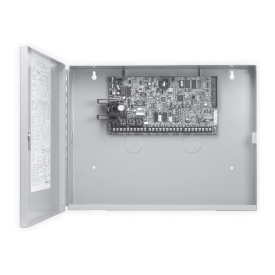
Mounting the Enclosure The metal enclosure for the XR100 Series must be mounted in a secure, dry place to protect the panel from damage due to tampering or the elements. It is not necessary to remove the XR100 Series PCB when installing the enclosure. Figure 2 shows the mounting hole locations for both the Model 350/350A Enclosures. Figure 3 shows the Model 341 Kiosk Enclosure. -
Page 13: Mounting Keypads And Zone Expansion Modules
To enable association operation in the XR100 panel, reset panel 3 times within 12 seconds. Allow the keypad bus Transmit/Receive LEDs to turn back on between each reset. For 60 seconds the panel listens for wireless keypads that are in the Installer Options Menu (3577 CMD) and have not been programmed, or associated into another panel. Those keypads are assigned to the first open device position automatically based upon the order in which they are detected. The keypad logo turns Green to indicate it has been associated with the panel. Digital Monitoring Products XR100 Series Canadian Installation Guide... -
Page 14: Primary Power Supply
Connect the transformer wires to terminals 1 and 2 on the panel. Use no more than 70 ft. of 16 gauge or 40 ft. of 18 gauge wire between the transformer and the XR100 Series. Always ground the panel before applying power to any devices: The XR100 Series must be properly grounded before connecting any devices or applying power to the panel. Proper grounding protects against Electrostatic Discharge (ESD) that can damage system components. -
Page 15: Secondary Power Supply
The leads need a momentary short only. Once the relay has pulled in, the battery voltage holds it in that condition. If the XR100 Series panel is powered up with an AC transformer, the battery cutoff relay is pulled in automatically. -
Page 16: Xr100 Series Canadian Power Requirements
XR100 Series Canadian Power Requirements During AC power failure, the XR100 Series panel and all connected auxiliary devices draw their power from the battery. All devices must be taken into consideration when calculating the battery standby capacity. The following table lists the XR100 Series panel power requirements. - Page 17 Total Standby ______ mA x number of Standby Hours needed ______ = _______ mA-hours Total Alarm ______ mA +_______ mA-hours Total _______ mA-hours .001 = _______ Amp-hrs Required Refer to section 6.9 for standby battery selection. Digital Monitoring Products XR100 Series Canadian Installation Guide...
-
Page 18: Standby Battery Selection
Note: If the Amp Hours Required calculation is greater than any Max. Ah Available number shown on a table, then add power supply(s) to power some system devices allowing the Amp Hours Required calculation to be reduced. See the 710 Bus Splitter/Repeater Installation Guide (LT-0310). Digital Monitoring Products XR100 Series Canadian Installation Guide... -
Page 19: Bell Output
Description XR100 Series panel terminals 7, 8, 9, and 10 are for the keypad bus. You can connect up to eight supervised keypads and multiple unsupervised keypads to the XR100 Series. In addition to DMP LCD keypads, you can also connect any combination of zone expansion modules to the data bus. Refer to the specific device installation sheet for the maximum number of... - Page 20 10.3 Zone Response Time A condition must be present on a zone for 500 milliseconds before it is detected by the XR100 Series panel. Ensure detection devices used on the protec tion zones are rated for use with this delay. Zones 1-10 can also be programmed for a fast response delay of 160 milliseconds.
- Page 21 B110PL, B401 8.5-35 9 & 10 715-16 (*) = Must be used in conjunction with System Sensor Polarity Reversal Module model RRS-M0D. See 1.19 for Installation Diagram Figure 6: Compatible 2-Wire Smoke Detectors Digital Monitoring Products XR100 Series Canadian Installation Guide...
- Page 22 13.3 Model 860 Relay Module Connect a Model 860 Relay Module to the J11 on the XR100 Series Canadian panel to provide relays for outputs 3-6. Use these relays for electrical isolation between the alarm panel and other systems or for switching voltage to control various functions.
- Page 23 J22 operation. J22 LX-Bus Enabled (Set One Interface Card J23 to “X”) Wireless- Zone Numbers LX-Bus Zone Numbers 500-599 500-599 15.4 LX-Bus LEDs The two LEDs, located near the bottom-right corner of J21 indicate data transmission and receipt. The top LED flashes green to indicate the panel is transmitting LX-Bus data. The bottom LED flashes yellow to indicate the panel is receiving LX-Bus data. 15.5 OVC LED The Overcurrent LED (OVC) lights Red when the devices connected to the Keypad Bus and LX-Bus(es) draw more current than the panel rating. The OVC is located above Outputs 1 and 2 on the panel and turns a steady Red when lit. When the OVC LED lights Red, the LX-Bus(es) and Keypad bus shut down. Digital Monitoring Products XR100 Series Canadian Installation Guide...
- Page 24 The ringer equivalence d. The device make, model, and serial number 17.4 Phone Line Monitor The XR100 Series panel has a built-in telephone monitor that monitors the phone line voltage to verify the connection to the central office. Figure 9 and the table below identify the phone block pin layout, wire numbers, and colors. To Telephone Wire Number...
- Page 25 15 16 17 18 21 22 25 26 Figure 10: XR100 Series Canadian Panel Showing the Reset Jumper 18.2 J4 Tamper Header The J4 header is for use with the optional DMP 306 Tamper Harness. The harness connects to one or more tamper switches mounted inside the panel enclosure to supervise against unauthorized enclosure opening or removal. Refer to the wiring diagram on the enclosure door for correct tamper switch wiring.
- Page 26 Use of the following zone expanders are permitted for connection of burglary devices: 710 Bus Splitter Module 714 Zone Expander, 4 zones 715 Zone Expander, 4 zones 7070(A)/7073(A) Keypads, 4 zones 711 Zone Expander, Single 714-8 Zone Expander, 8 zones 715-8 Zone Expander, 8 zones 7170/7173 Keypads, 4 zones 712-8 Zone Expander, 8 714-16 Zone Expander, 16 zones 715-16 Zone Expander, 16 zones Digital Monitoring Products XR100 Series Canadian Installation Guide...
-
Page 27: 23.1 Ulc Installation Recommendations
7. Products or components of products used in communication channels, which perform communications functions only, shall comply with the requirements applicable to communications equipment as specified in CAN/CSA-C22.2 No. 60950-1, Information Technology Equipment-Safety - Part 1: General Requirements. Such products or components include, but are not limited to: A Hubs; B Routers; C Network interface devices; D Third party communications service providers; E Digital subscriber line (DSL) modems; and F Cable modems Digital Monitoring Products XR100 Series Canadian Installation Guide... -
Page 28: False Alarm Reduction Programmable Options
Yes as required 4.3.3 Fire Alarm 15.4 Zone Type Required Option FV Type Zone (unless sensors can Verification self verify) 3.19 Telephone Include *70P in Enabled if user has 4.5 Call Waiting Cancel Required Option Disabled Number Telephone Number call waiting * Programming at installation may be subordinate to other UL requirements for the intended application. ** For listed installations, combined Entry Delay and Transmit Delay should not exceed 1 minute. Digital Monitoring Products XR100 Series Canadian Installation Guide... -
Page 29: Call Waiting (Ansi/Sia Cp-01-2010)
(LT-0896CAN). 24.5 Minimum Installation Requirements (ANSI/SIA CP-01-2010) SIA CP-01-2010 minimum system installation requirements include an XR100 Series, a listed local Bell, and off premise DACT communication to an SCS-1R receiver plus one of the following compatible keypads. 630F Fire Command™ Center 7060, 7063, 7070, or 7073 Thinline™... -
Page 30: Wiring Diagrams
GRN BLK SMK GND Z9+ Z9- Z10+ Z10- Each LX-Bus Module must have its own independent address ranging from 00 to 99. A Supervisory zone must be programmed into the XR100 Series to properly supervise each module. To additional Yellow LX-Bus... -
Page 31: 25.2 Model 860 Relay Module Connection
1k EOL Zone 1 Programming Night Type Zone (NT) Disarmed Open (DO) Zone 1 Disarmed Short (DS) 1k EOL Armed Open (AO) Armed Short (AS) Note: Zone Names must be same or equivalent Digital Monitoring Products XR100 Series Canadian Installation Guide... -
Page 32: 25.4 Canadian Fire Communicator For Facp
Form C contacts activate open on Zone 3 Common AC Trouble condition. 1k Ohm EOL Normally Closed Supervisory Normally Open Zone 4 Form C contacts activate short on Common Supervisory condition. 1k Ohm EOL Normally Closed Digital Monitoring Products XR100 Series Canadian Installation Guide... -
Page 33: 25.5 Combination S304 And S559 System
Burglary inputs Normally Closed No Fire Devices Normally Open Relay contacts to See 21.5 Zone Expansion for a Common list of approved expanders panel zones Normally Closed Normally Open Common Normally Closed Digital Monitoring Products XR100 Series Canadian Installation Guide... -
Page 34: 25.6 System Sensor 2-Wire Smoke Detectors
SYSTEM SENSOR LOOP OUT + TEST & MAINTENANCE MODULE OUT - IN + IN - 3.3K Z10+ Z10- 470 Ohm or (2) 1k in Parallel Orange Yellow 3.9K EOL SYSTEM SENSOR 2WTA-B SMOKE DETECTORS Digital Monitoring Products XR100 Series Canadian Installation Guide... -
Page 35: Revisions To This Document
1.5 LX-Bus Added Model 2W-BLX and 2WT-BLX Smoke Detector references 3.4 Accessory Devices Added Model 2W-BLX and 2WT-BLX Smoke Detector references 6.8 XR100 Series Canadian Power Added Model 2W-BLX and 2WT-BLX Smoke Detector references Requirements 1.19 Complete Guide Added 464 Series references 3.4 Accessory Devices Updated for current products 6.8 XR100 Series Canadian Power Updated for current products Requirements 1.18 6.1 Battery Terminal 3 and 4 Updating model 368 6.9 Standby Battery Selection Updating model 368 1.17 Entire Document Removed 463C references 25.1 LX-Bus Module Connection Updated diagram and added DMP Interface Cards 1.16... - Page 36 Certifications This Class A digital apparatus complies with Canadian ICES-003 ANSI/SIA CP-01-2010 False Alarm Reduction ULC-S559-04 Equipment for Fire Signal Receiving Centers and Systems ULC S545 Household Fire Subject-C1023 Household Burglar ULC/ORD-C1076 Proprietary Burglar ULC S304 Central Station Burglar 800-641-4282 IN TRU SIO N • F IRE • ACC ESS • NET WOR KS www.dmp.com 2500 North Partnership Boulevard Designed, Engineered and...
Need help?
Do you have a question about the XR100 Series and is the answer not in the manual?
Questions and answers