Table of Contents
Advertisement
Advertisement
Table of Contents

Related Manuals for United Technologies Carrier 30RQM 160

Summary of Contents for United Technologies Carrier 30RQM 160
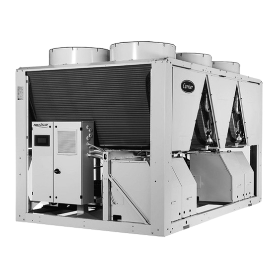
- Page 1 I N S TA L L AT I O N , O P E R AT I O N A N D M A I N T E N A N C E I N S T R U C T I O N S Unit with low-noise option Reversible air-to-water heat pump 30RQM 160-520 A...
-
Page 2: Table Of Contents
CONTENTS 1 - INTRODUCTION .................................... 4 1.1 - Specific features of 30RQP units .............................. 4 1.2 - Installation safety considerations .............................. 4 1.3 - Pressure equipment and components............................5 1.4 - Repair safety considerations ..............................6 2 - PRELIMINARY CHECKS ................................8 2.1 - Check equipment received ................................ 8 2.2 - Handing and positioning ................................8 2.3 ... - Page 3 CONTENTS 9 - MAIN COMPONENTS OF THE UNIT AND OPERATING CHARACTERISTICS ................ 41 9.1 - Compressors ................................... 41 9.2 - Lubricant....................................41 9.3 - Air coils ....................................41 9.4 - Fans ......................................41 9.5 - Electronic expansion valve (EXV) ............................42 9.6 - Moisture indicator ..................................42 9.7 ...
-
Page 4: Introduction
1 - INTRODUCTION Prior to the initial start-up of the 30RQM/30RQP units, everyone atmospheric agents (water can form rust or ice). These involved in the works should be thoroughly familiar with these devices, as well as the drain piping, must not impair operation instructions and with the characteristics of the installation site, and and must not lead to a pressure drop that is higher than 10% ensure these are respected. -
Page 5: Pressure Equipment And Components
1 - INTRODUCTION 1.3 - Pressure equipment and components specifically trained on this equipment and system. All welding operations must be carried out by qualified specialists. These products incorporate equipment or components under 30RQM/30RQP units use high pressure R-410A refrigerant (the pressure, manufactured by Carrier or other manufacturers. We unit operating pressure is above 40 bar; the pressure at an air recommend that you contact your professional body to find out ... -
Page 6: Repair Safety Considerations
1 - INTRODUCTION OPERATING CHECKS: Please contact Carrier Service for this type of test. The test • I M P O RTA N T I N F O R M AT I O N R E G A R D I N G T H E principle set out here by Carrier does not involve removal of the ... - Page 7 1 - INTRODUCTION Charging any refrigerant other than the original type (R410A) It is dangerous and illegal to re-use disposable (non- will impair machine operation and can even cause irreparable returnable) cylinders or attempt to refill them. When cylinders damage to the compressors. The compressors operating with are empty, evacuate the remaining gas pressure, and move this refrigerant type are lubricated with a synthetic polyolester them to a designated place for recovery.
-
Page 8: Preliminary Checks
2 - PRELIMINARY CHECKS 2.1 - Check equipment received 2.2 - Handing and positioning ■ Check that the unit has not been damaged during transport 2.2.1 - Handling and that no parts are missing. If the unit has been damaged or the shipment is incomplete, send a claim to the shipping See the section on “Installation safety considerations”. company. -
Page 9: Checks Before System Start-Up
2 - PRELIMINARY CHECKS Before positioning the unit, check that: - Verify that all documents for pressure containers, certificates, - The chosen location can support the weight of the unit, or name plates, register, instruction manuals and documentation that appropriate reinforcement measures have been taken. provided by the manufacturer to comply with the regulations - The unit is installed level on an even surface (maximum are present. tolerance is 5 mm along both axes). - Verify that access and safety routes are unobstructed. - If the support structure is sensitive to vibration and/or noise - Verify the instructions and guidelines to prevent the deliberate transmission it is advisable to insert anti-vibration mounts discharge of refrigerant. -
Page 10: Dimensions And Clearances
3 - DIMENSIONS AND CLEARANCES 3.1 - 30RQM/30RQP 160-230 WITHOUT HYDRAULIC MODULE 30RQP only Sizes 210-230 Power connection WITH HYDRAULIC MODULE 210-230 ONLY 30RQP ONLY NOTE: Legend All dimensions are given in mm. Non-contractual drawings. Clearances required for maintenance and air flow When designing a system, refer to the certified dimensional Clearance recommended for coil removal drawings provided with the unit or available on request. Water inlet Please refer to the certified dimensional drawings for the Water outlet... - Page 11 3 - DIMENSIONS AND CLEARANCES WITH WATER BUFFER TANK MODULE Main hydraulic connection Electrical power connection NOTE: Legend All dimensions are given in mm. Non-contractual drawings. Clearances required for maintenance and air flow When designing a system, refer to the certified dimensional Clearance recommended for coil removal drawings provided with the unit or available on request. Water inlet Please refer to the certified dimensional drawings for the Water outlet positioning of the fixing points, weight distribution points Air outlet, do not obstruct...
-
Page 12: 30Rqm/30Rqp 240-330
3 - DIMENSIONS AND CLEARANCES 3.2 - 30RQM/30RQP 240-330 WITHOUT HYDRAULIC MODULE 30RQP only Size 330 Power connection Sizes 270-310-330 WITH HYDRAULIC MODULE NOTE: Legend All dimensions are given in mm. Non-contractual drawings. Clearances required for maintenance and air flow When designing a system, refer to the certified dimensional Clearance recommended for coil removal drawings provided with the unit or available on request. Water inlet Please refer to the certified dimensional drawings for the Water outlet... - Page 13 3 - DIMENSIONS AND CLEARANCES WITH WATER BUFFER TANK MODULE Main hydraulic connection Electrical power connection NOTE: Legend All dimensions are given in mm. Non-contractual drawings. Clearances required for maintenance and air flow When designing a system, refer to the certified dimensional Clearance recommended for coil removal drawings provided with the unit or available on request. Water inlet Please refer to the certified dimensional drawings for the Water outlet positioning of the fixing points, weight distribution points Air outlet, do not obstruct...
-
Page 14: 30Rqm/30Rqp 380-520
3 - DIMENSIONS AND CLEARANCES 3.3 - 30RQM/30RQP 380-520 WITHOUT HYDRAULIC MODULE 30RQP only Sizes 430-470-520 Power connection WITH HYDRAULIC MODULE Legend NOTE: All dimensions are given in mm. Non-contractual drawings. Clearances required for maintenance and air flow When designing a system, refer to the certified dimensional Clearance recommended for coil removal drawings provided with the unit or available on request. Water inlet Please refer to the certified dimensional drawings for the Water outlet... -
Page 15: Installation Of Multiple Heat Pumps
3 - DIMENSIONS AND CLEARANCES WITH WATER BUFFER TANK MODULE Main hydraulic connection Electrical power connection NOTE: Legend All dimensions are given in mm. Non-contractual drawings. Clearances required for maintenance and air flow When designing a system, refer to the certified dimensional Clearance recommended for coil removal drawings provided with the unit or available on request. Water inlet Please refer to the certified dimensional drawings for the Water outlet positioning of the fixing points, weight distribution points Air outlet, do not obstruct... -
Page 16: Physical And Electrical Data For 30Rqm And 30Rqp Units
4 - PHYSICAL AND ELECTRICAL DATA FOR 30RQM AND 30RQP UNITS 4.1 - Physical data 30RQM 160-520 30RQM Sound levels Standard unit Sound power dB(A) Sound pressure at 10 m dB(A) Standard unit + option 15 Sound power dB(A) Sound pressure at 10 m dB(A) Dimensions Length 2410 3604 4797 Width 2253 2253... -
Page 17: Physical Data 30Rqp 160-520
4 - PHYSICAL AND ELECTRICAL DATA FOR 30RQM AND 30RQP UNITS 4.2 - Physical data 30RQP 160-520 30RQP Sound levels Standard unit Sound power dB(A) Sound pressure at 10 m dB(A) Standard unit + option 15 Sound power dB(A) Sound pressure at 10 m dB(A) Standard unit + option 15LS Sound power dB(A) Sound pressure at 10 m... -
Page 18: Electrical Data 30Rqm 160-520
4 - PHYSICAL AND ELECTRICAL DATA FOR 30RQM AND 30RQP UNITS 4.3 - Electrical data 30RQM 160-520 30RQM Power circuit Nominal voltage V-ph-Hz 400 - 3 - 50 Voltage range 360 - 440 Control circuit supply 24 V via internal transformer Nominal unit current draw Circuit A&B Maximum unit input power Circuit A&B Cosine Phi unit at maximum power 0,88... -
Page 19: Short Circuit Stability Current
4 - PHYSICAL AND ELECTRICAL DATA FOR 30RQM AND 30RQP UNITS 4.5 - Short circuit stability current Short circuit stability current (TN system(1)) 30RQM/30RQP Rated Short-Time Withstand Current (Icw), (1s) rms value/peak lpk Circuits A & B kA/kA 8/30 8/30 8/30 8/30 8/30 8/30 15/65 15/65 15/65 15/65 20/80 20/80 With fuses upstream - maximum fuse values assigned (gL/gG) Circuits A & B... - Page 20 4 - PHYSICAL AND ELECTRICAL DATA FOR 30RQM AND 30RQP UNITS For the low pressure dual-pump motors for 30RQM/30RQP 160-520 units (option 116U) 30RQM/30RQP Description Units 160 180 210 230 240 270 310 330 380 430 470 Nominal efficiency at full load and nominal voltage 85,9 86,4 87,5 87,5 87,5 87,5 87,5 89,6 89,6 89,6 89,7 89,7 Nominal efficiency at 75% full load and nominal voltage 86,4 86,9 88,2 88,2 88,2 88,2 88,2 90,4 90,4 90,4 90,0 90,0 Nominal efficiency at 50% full load and nominal voltage...
-
Page 21: Compressor Usage And Electrical Data
4 - PHYSICAL AND ELECTRICAL DATA FOR 30RQM AND 30RQP UNITS For the high pressure single- and dual-pump motors for 30RQM/30RQP 160-520 units (options 116S and 116W) 30RQM/30RQP Description Units 160 180 210 230 240 270 310 330 380 430 Nominal efficiency at full load and nominal voltage 87,5 87,5 89,6 89,6 89,6 89,7 89,7 89,7 90,8 90,8 90,8 90,8 Nominal efficiency at 75% full load and nominal voltage... -
Page 22: Electrical Connection
5 - ELECTRICAL CONNECTION 5.2 - Voltage phase imbalance (%) Please refer to the certified dimensional drawings, supplied with the unit. 100 x max. deviation from average voltage Average voltage 5.1 - Power supply Example: The power supply must conform to the specification on the heat pump nameplate. The supply voltage must be within the range On a 400 V - 3 ph - 50 Hz supply, the individual phase voltages specified in the electrical data table. For connections, refer to the were measured with the following values: wiring diagrams and certified dimensional drawings. AB = 406 V; BC = 399 V; AC = 394 V WARNING: Operation of the heat pump with an incorrect Average voltage = (406 + 399 + 394)/3 = 1199/3 supply voltage or excessive phase imbalance constitutes misuse which will invalidate the Carrier warranty. -
Page 23: Recommended Wire Sections
5 - ELECTRICAL CONNECTION 5.4 - Recommended wire sections The study includes the standardised installation cases according to IEC 60364: cables with PVC (70°C) or XLPE insulation (90°C) Wire sizing is the responsibility of the installer, and depends on with copper core; routing in accordance with table 52C of the the characteristics and regulations applicable to each installation standard. The maximum ambient temperature is 45°C. The site. The following is only to be used as a guideline, and does not maximum length mentioned is calculated to limit the voltage drop make Carrier in any way liable. After wire sizing has been to 5 %. -
Page 24: Power Cable Access Routing
5 - ELECTRICAL CONNECTION 5.5 - Power cable access routing 5.6 - Field control wiring The power cables are routed into the electrics box on 30RQM/30RQP IMPORTANT: Field connection of interface circuits carries units from underneath. safety risks: any modifications to the electrical box must ensure that the equipment remains compliant with local A removable aluminium plate on the base of the electrical cabinet ... -
Page 25: Application Data
6 - APPLICATION DATA 6.1 - Operating range 30RQM/30RQP 160-520 units - Heating mode 30RQM/30RQP 160-520 units, cooling mode Minimum Maximum Water heat exchanger Water inlet temperature at start-up °C Water outlet temperature during operation °C Leaving water temperature during operation °C low-temperature brine solution option Air heat exchanger Ambient operating temperature - 30RQM °C (4)(6) -
Page 26: Maximum Water Flow (Units Without Hydraulic Module)
6 - APPLICATION DATA 6.3 - Maximum water flow (units without 6.6 - Maximum system water volume hydraulic module) Units supplied with a hydraulic module may include an expansion The maximum water flow is shown in the table on the next page. tank which limits the volume in the water loop (option 293). If the system's flow exceeds the unit's maximum value, it can be The table below gives the maximum loop volume for pure water bypassed as shown in the diagram. or ethylene glycol depending on the system's various concentrations and static pressures.. If the maximum volume is insufficient, For maximum water flow compared to the minimum system water loop volume, an additional expansion tank vessel must be added to the system. -
Page 27: Pressure Drop Curves For The Exchanger And Standard Water Inlet/Outlet Piping
6 - APPLICATION DATA 30RQM/30RQP 160-520 units with high pressure hydraulic module Maximum flow rate (l/s) Minimum flow 30RQM/30RQP rate (l/s) Single Dual 11,7 10,8 11,7 10,8 16,1 15,5 16,1 15,5 16,1 15,5 26,5 26,5 26,5 26,5 26,5 26,5 26,5 29,2 26,7 29,2... -
Page 28: Water Connections
7 - WATER CONNECTIONS 7.1 - Operating precautions and recommendations When connecting units to the water distribution pipe work, refer to the certified dimensional drawings supplied with the unit for the Before any system start-up, verify that the hydraulic circuits are dimensions and position of the water inlet and outlet connections. connected to the appropriate heat exchangers. The water circuit The pipes and tubes should not transmit any axial or radial forces should be designed to have the least number of elbows and to the exchangers or any vibrations. changes in elevation; the main points to be checked for the The water must be analysed and the circuit must include provision connection are listed below. -
Page 29: Hydraulic Connections
7 - WATER CONNECTIONS 7.2 - Hydraulic connections The hydraulic module options are only compatible with closed heat transfer fluid loops. The use of the hydraulic kit on open loop systems is prohibited. Schematic diagram of the water circuit without the hydraulic module Schematic diagram of the water circuit with the hydraulic module Option Option... - Page 30 7 - WATER CONNECTIONS Figure 1: Water connections without hydraulic module Figure 2: Water connections with hydraulic module Example: Single-pump Example: Dual-pump Presence of the Coupling for stainless steel filter Coupling for expansion vessel Presence of the expansion vessel stainless steel filter (option 293) (option 293) See legend on the previous page. Figure 3: Water connections with hydraulic module and with buffer tank module option...
-
Page 31: Water Flow Detection
7 - WATER CONNECTIONS 7.3 - Water flow detection Combination of options for the periods when the machine is in standby mode. 7.3.1 - Standard unit 30RQM/30RQP 160-520 Ambient unit temperature range without option 116 with option 116 All units are equipped with a factory-set flow switch. It cannot be > 0°C to 48°C adjusted on site. Option 41 Option 42A A water pump operating interlock must be wired to the unit if no ... -
Page 32: Protection Against Cavitation (With Option 116)
7 - WATER CONNECTIONS 7.5 - Protection against cavitation (with option An installation in series is only possible with a fixed speed pump 116) (example 3): - The operation of the pump will be controlled by the Master To ensure the durability of pumps fitted on the integrated hydraulic unit. modules, the control algorithm of 30RQM/30RQP units includes - The Master-Slave assembly is controlled on the water outlet protection against cavitation. It is therefore necessary to ensure without additional sensor. a minimum pressure of 60 kPa (0.6 bar) at the pump inlet both - The installation must be carried out only according to the when shut down and during operation. A pressure below 60 kPa diagram given in the example 3. will prevent unit start-up, or will cause an alarm and shut-down. A IMPORTANT: pressure below 100 kPa will trigger an alert on the user interface. Both of the units must be equipped with option 58 to allow To obtain an adequate pressure, it is recommended: master/slave operation. -
Page 33: Auxiliary Electric Heaters
7 - WATER CONNECTIONS Example 3: operation in series - control on water Example of additional electric heaters outlet for a combination of units Legend Operating range for which the heat pump output is less than the building thermal Master unit load Operating range for which the heat pump output is greater than the building Slave unit thermal load Electrical boxes for Master and Slave units... -
Page 34: Nominal System Water Flow Control
8 - NOMINAL SYSTEM WATER FLOW CONTROL Refer to the diagram in the "Hydraulic connections" section - Remove the air from the circuit (item 5). for all references points mentioned in this chapter. - Repeat until all fouling is removed from the filter. The water circulation pumps of 30RQM/30RQP units have been 8.1.3 - Procedure for controlling the water flow designed to allow the hydraulic modules to operate over a range of possible configurations based on specific installation conditions, Once the circuit is cleaned, read the pressures on the pressure i.e. with temperature differences between the water inlet and outlet ... -
Page 35: Units With Hydraulic Module And Variable Speed Pump - Pressure Differential Control
8 - NOMINAL SYSTEM WATER FLOW CONTROL NOTE: - Perform another reading of the flow and compare this value with the initial value. A decrease in the flow value indicates If the network has an excessive pressure drop in relation to that the filters in the system need to be removed and cleaned. the available static pressure delivered by the unit pump, the In this case, close the shut-off valves on the water inlet and nominal water flow cannot be obtained (lower resulting flow) outlet (item 16) and remove the filters (items 17 and 1) after ... -
Page 36: Units With Hydraulic Module And Variable Speed Pump - Setting A Fixed Flow For The System
8 - NOMINAL SYSTEM WATER FLOW CONTROL 8.5 - Units with hydraulic module and variable speed pump – Setting a fixed flow for the system The flow will be set to a nominal value. This value shall remain constant, and will not be dependent on variations in the installation's load. Contact Carrier Service to discuss the implementation of the procedures set out below. -
Page 37: Pump Pressure/Flow Rate Curves
8 - NOMINAL SYSTEM WATER FLOW CONTROL 8.6 - Pump pressure/flow rate curves Units with hydraulic module (fixed speed pump or variable speed pump at 50 Hz) Data applicable for: - Fresh water at 20°C. - Refer to the chapter "Exchanger water flow" for the maximum water flow values. - In case of use of ethylene-glycol, the maximum flow rate is reduced. 8.6.1 - 30RQM/30RQP high pressure pumps Single pumps Water flow rate, l/s 1 30RQM/30RQP 160-180 2 30RQM/30RQP 210-230-240 3 30RQM/30RQP 270-310-330-380 4 30RQM/30RQP 430-470 5 30RQM/30RQP 520 Dual pumps Water flow rate, l/s 1 ... - Page 38 8 - NOMINAL SYSTEM WATER FLOW CONTROL 8.6.2 - 30RQM/30RQP low pressure pumps Single pumps Water flow rate, l/s 1 30RQM/30RQP 160-180 2 30RQM/30RQP 210-230 3 30RQM/30RQP 240-270-310 4 30RQM/30RQP 330-380-430 5 30RQM/30RQP 470-520 Dual pumps B C D Water flow rate, l/s 1 30RQM/30RQP 160 2 30RQM/30RQP 180 3 30RQM/30RQP 210-230 4 30RQM/30RQP 240-270-310 5 ...
-
Page 39: Available Static System Pressure
8 - NOMINAL SYSTEM WATER FLOW CONTROL 8.7 - Available static system pressure Units with hydraulic module (fixed speed pump or variable speed pump at 50 Hz) Data applicable for: - Fresh water at 20°C. - Refer to the chapter "Water exchanger water flow" for the maximum water flow values. - In case of use of ethylene-glycol, the maximum flow rate is reduced. 8.7.1 - 30RQM/30RQP high pressure pumps Single pumps Sizes 160-240 Sizes 270-520 B C D E Water flow rate, l/s F G H Water flow rate, l/s 1 ... - Page 40 8 - NOMINAL SYSTEM WATER FLOW CONTROL 8.7.2 - 30RQM/30RQP low pressure pumps Single pumps Sizes 160-270 Sizes 310-520 B C D Water flow rate, l/s G H I Water flow rate, l/s 1 30RQM/30RQP 160-180 5 30RQM/30RQP 310 2 30RQM/30RQP 210 6 30RQM/30RQP 330-380-430 3 30RQM/30RQP 230 7 30RQM/30RQP 470 4 30RQM/30RQP 240-270 8 ...
-
Page 41: Main Components Of The Unit And Operating Characteristics
9 - MAIN COMPONENTS OF THE UNIT AND OPERATING CHARACTERISTICS 9.1 - Compressors If this is not the case, there might be a leak or an oil trap in the circuit. If there is an oil leak, find and repair it, then refill with 30RQM/30RQP units use hermetic scroll compressors. Each refrigerant and oil. compressor is equipped as standard with a crankcase oil heater, See the Service Guide for the oil removal and refill procedures. and ... -
Page 42: Electronic Expansion Valve (Exv)
9 - MAIN COMPONENTS OF THE UNIT AND OPERATING CHARACTERISTICS In accordance with regulation No. 640/2009 and amendment 4/2014 implementing Directive 2009/125/EC concerning eco-design requirements for electric motors Product 30RQM 30RQM 30RQP 30RQP Option Standard Option 28 Standard Option 12 Motor type Asynchronous Asynchronous Asynchronous Asynchronous Number of poles Nominal input frequency Nominal voltage... -
Page 43: Low Temperature And Brine Solution Option (Option 6B)
9 - MAIN COMPONENTS OF THE UNIT AND OPERATING CHARACTERISTICS 9.13 - Low temperature and brine solution Minimum frost protection temperature based on the option (Option 6B) leaving water temperature (example) Brine solution production from 0°C to -8°C is only possible with the low-temperature brine solution option (6B). The unit is equipped with insulation on the suction tubes. The insulation ... -
Page 44: Fan Arrangement
9 - MAIN COMPONENTS OF THE UNIT AND OPERATING CHARACTERISTICS 9.14 - Fan arrangement 30RQM/30RQP 30RQM/30RQP 240-270 30RQM/30RQP 160 180-210-230 CKT A CKT B CKT A CKT B CKT A CKT B 30RQM/30RQP 310-330 30RQM/30RQP 380 30RQM/30RQP 430-470-520 CKT A CKT B CKT A CKT B... -
Page 45: Options
10 - OPTIONS 10.1 - Hydraulic module without variable speed The performances (capacities, efficiencies) depend on the speed (options 116R, 116S, 116T, 116U) of the fans, then on the duct pressure drop: - Between 0 and 100 Pa, the unit performance is only slightly The hydraulic module is composed of the system's main hydraulic affected components: factory-fitted screen filter, relief valve and water - Between 100 and 200 Pa, the unit performance may vary pump. ... -
Page 46: Nominal And Maximum Air Flows Per Circuit (A And B) For 30Rqp Sizes
10 - OPTIONS 10.5 - Nominal and maximum air flows per circuit (A and B) for 30RQP sizes Circuit A Circuit B 30RQP Nominal/maximum air flow (l/s) Nominal/maximum air flow (l/s) 4767 / 5720 9534 / 11441 180-230 9534 / 11441 9534 / 11441 240-270 9534 / 11441 14301 / 17161 310-330 9534 / 11441 19068 / 22882 14301 / 17161... - Page 47 10 - OPTIONS Principle of the installation of the ducts Solution 1 Solution 2 each fan has its own duct 2 fans can used the same duct Fan motor access hatches (provide a 700 x 700 mm hatch) for each single and dual duct Rules for a correct ductwork Fan motor electrical protection - Each ...
-
Page 48: Partial Heat Reclaim Using Desuperheaters (Option 49)
10 - OPTIONS 10.7 - Partial heat reclaim using desuperheaters (option 49) This option permits the production of free hot water using heat reclaim by desuperheating the compressor discharge gases. The option is available for the whole 30RQM/30RQP range. A plate heat exchanger is installed in series with the air heat exchanger coils on the compressor discharge line of each circuit. The control configuration for the desuperheater option is factory assembled (see chapter 10.7.8 "Control c onfiguration"). The installer must protect the heat exchanger against frost. 10.7.1 - Physical data, 30RQM/30RQP units with partial heat reclaim using desuperheaters (option 49) 30RQM/30RQP Desuperheater in circuits A/B Plate heat exchanger 3,75 3,75 3,75 3,75... - Page 49 10 - OPTIONS 10.7.2 - 30RQM/30RQP 160-230 (equipped with desuperheater option 49) 2'' Victaulic 2410 HT Unit with hydraulic module Unit without hydraulic module 1500 Legend All dimensions are given in mm. Clearances required for maintenance and air flow Clearance recommended for coil removal Water inlet Water outlet Control box NOTE: Non-contractual drawings. When designing a system, refer to the certified dimensional drawings provided with the unit or available on request.
- Page 50 10 - OPTIONS 10.7.3 - 30RQM/30RQP 240-330 (equipped with desuperheater option 49) 2'' Victaulic 3604 HT Unit with hydraulic module Unit without hydraulic module 1495 1500 Legend All dimensions are given in mm. Clearances required for maintenance and air flow Clearance recommended for coil removal Water inlet Water outlet Control box NOTE: Non-contractual drawings. When designing a system, refer to the certified dimensional drawings provided with the unit or available on request.
- Page 51 10 - OPTIONS 10.7.4 - 30RQM/30RQP 380-520 (equipped with desuperheater option 49) 2'' Victaulic 4797 HT Unit with hydraulic module Unit without hydraulic module 1500 2730 Legend All dimensions are given in mm. Clearances required for maintenance and air flow Clearance recommended for coil removal Water inlet Water outlet Control box NOTE: Non-contractual drawings. When designing a system, refer to the certified dimensional drawings provided with the unit or available on request.
- Page 52 10 - OPTIONS 10.7.5 - Installation and operation of the heat reclaim During the unit installation the heat reclaim plate heat with desuperheater option exchangers must be insulated and frost protected, if required. Please refer to the typical installation diagram below for the main The 30RQM/30RQP units with the desuperheater option (No. 49) components and functions of the 30RQM/30RQP units with the are supplied with one heat exchanger per refrigerant circuit. desuperheater option. Typical installation diagram of units with the desuperheater option Heating mode Cooling mode &...
- Page 53 10 - OPTIONS 10.7.6 - Installation 10.7.7 - Operating range The water supply of each desuperheater is arranged in parallel. Cooling mode Minimum Maximum The water connections on the desuperheater water inlets and Water heat exchanger (evaporator) outlets must not cause any mechanical local constraint at the heat Entering water temperature at start-up °C exchangers. If necessary, install flexible connection sleeves.
-
Page 54: Other Options
10 - OPTIONS 10.8 - Other options Options Description Advantages Improved corrosion resistance, Corrosion protection, Fins made of pre-treated aluminium 30RQM/30RQP recommended for moderate marine and traditional coils (polyurethane and epoxy) 160-520 urban environments 30RQP Low-temperature brine Low temperature chilled water production Covers specific applications such as ice 180-230-270- solution down to -8°C with ethylene or propylene glycol storage and industrial processes Unit equipped with high static variable-speed Ducted fan discharge, optimised Unit equipped for air fans (maximum 200 Pa), each fan equipped condensing or evaporating temperature 30RQP 160-520 discharge ducting with a connection flange allowing the control, based on the operating conditions connection to the ducting system. and system characteristics Aesthetic and sound absorbing compressor ... - Page 55 10 - OPTIONS Options Description Advantages Easy and high-speed connection by Two-directional high-speed communication ethernet line to a building management 30RQM/30RQP Bacnet over IP gateway using BACnet protocol over Ethernet network system. Allows access to multiple unit 160-520 (IP) parameters Easy and high-speed connection by 149B Bi-directional high-speed communication using ethernet line to a building management 30RQM/30RQP Modbus over IP and RS485 Modbus protocol over Ethernet network (IP) system. Allows access to multiple unit 160-520 parameters Control board with additional inputs/outputs. Extended remote control capabilities 30RQM/30RQP Energy Management Module See Energy Management Module option ...
-
Page 56: Standard Maintenance
11 - STANDARD MAINTENANCE To ensure optimal efficiency and reliability of the equipment and Electrical checks (annual checks): all its functions, we recommend establishing a maintenance - At least once a year tighten the electrical connections for the contract with your local Carrier Service organisation. This contract power supply circuits (see tightening torques table), will include regular inspections by Carrier Service specialists so - Check and tighten all control connections, if required, that any malfunction is detected and corrected quickly, ensuring - Check the labelling of the system and instruments, re-apply that no serious damage can occur. A Carrier Service maintenance the missing labels if required, contract is the best way to ensure the maximum operating life for - Remove the dust and clean the interior of the electrical boxes. your equipment and, through the expertise of Carrier's qualified Be careful not to blow dust or debris into components; use personnel, provides the ideal way to manage your system energy a brush and vacuum wherever possible, consumption effectively. - Clean the insulators and bus bar supports (dust combined The refrigeration equipment must be sericed by professionals; with ... -
Page 57: Level 3 (Or Higher) Maintenance
11 - STANDARD MAINTENANCE 11.3 - Level 3 (or higher) maintenance 11.6 - Air coil Maintenance at this level requires specific skills, qualifications, We recommend that coils with fins are inspected regularly to check tools and expertise. Only the manufacturer, his representative or the degree of cleanliness. This depends on the environment where authorised agent are permitted to carry out this work. the unit is installed, in particular urban and industrial sites, and for units installed near trees that shed their leaves. This maintenance work relates to the following: - Replacement of major components (compressor, water heat Recommendations for maintenance and cleaning of RTPF exchanger), coils: - Operations on the refrigerant circuit (handling refrigerant), - Modification of factory-set parameters (change of application),... -
Page 58: Variable Frequency Drive Maintenance
11 - STANDARD MAINTENANCE 11.8 - Variable frequency drive maintenance frequency drive, contact Carrier Service. The variable drives fitted on 30RQM/30RQP units do not require CAUTION: Before any work on the variable drive, ensure that a dielectric test, even if being replaced: they are systematically the circuit is isolated and there is no voltage present verified before delivery. Moreover, the filtering components (reminder: capacitor discharge time: approximately 5 minutes installed ... -
Page 59: Final Shutdown
12 - FINAL SHUTDOWN 12.1 - Shutting down Separate the units from their energy sources, allow them to cool then drain them completely. 12.2 - Recommendations for disassembly Use the original lifting equipment. Sort the components according to their material for recycling or disposal, in accordance with regulations in force. Check whether any part of the unit can be recycled for another purpose. 12.3 - Fluids to be recovered for treatment - Refrigerant - Heat-transfer fluid: depending on the installation, water, brine solution, etc. - Compressor oil 12.4 - Materials to be recovered for recycling - Steel - Copper - Aluminium... -
Page 60: Unit Start-Up Checklist For Installers Prior To Contacting Carrier Service
13 - UNIT START-UP CHECKLIST FOR INSTALLERS PRIOR TO CONTACTING CARRIER SERVICE (USE FOR MACHINE FILE) Preliminary information Job name: ........................................ Location: ........................................Installing contractor: ....................................Distributor: ....................................... Start-up performed by.............. D ate ..................... Equipment Model 30RQM/30RQP ..............Serial number ................Compressors Circuit A Circuit B 1. Model .................. 1 . Model ..................Serial number ................ - Page 61 13 - UNIT START-UP CHECKLIST FOR INSTALLERS PRIOR TO CONTACTING CARRIER SERVICE Unit start-up The chilled water pump contactor has been correctly cabled with the chiller The oil level is correct The unit has been checked for leaks (including couplings) Locate, repair, and report any refrigerant leaks ..............................................................................................................................Check voltage imbalance: AB.... AC.... BC.... Average voltage = ...... (see installation instructions) Maximum deviation = .... (see installation instructions) Voltage imbalance = ..... (see installation instructions) Voltage imbalance is less than 2% WARNING Do not start the chiller if the voltage imbalance is greater than 2%. Contact your local power company for assistance. All incoming power voltage is within the nominal voltage range The compressor crankcase heaters have been running for 6 hours Check of the evaporator water loop...
- Page 62 13 - UNIT START-UP CHECKLIST FOR INSTALLERS PRIOR TO CONTACTING CARRIER SERVICE Carry out the QUICK TEST function (Consult Carrier Service): Check and log on to the user menu configuration Load sequence selection ..................................Capacity ramp loading selection................................Start-up delay ......................................Pump control ......................................Setpoint shift mode ....................................Night mode capacity limitation ................................. Re-enter the setpoints To start up the cooler Warning...
- Page 64 CARRIER participates in the ECP programme for LCP/HP Check ongoing validity of certificate: www.eurovent-certification.com www.ecodesign.hvac.carrier.com Order No.: 10018, 05.2019. Supersedes order No.: 10018, 11.2018. Manufactured by: Carrier SCS, Montluel, France. Manufacturer reserves the right to change any product specifications without notice. Printed in the European Union.
Need help?
Do you have a question about the Carrier 30RQM 160 and is the answer not in the manual?
Questions and answers