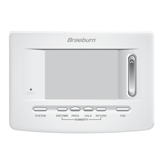
Braeburn Premier Series Detailed Installer Manual
Up to 2 heat/1 cool heat pump 1 heat/1 cool conventional with humidity control
Hide thumbs
Also See for Premier Series:
- Installer's manual (20 pages) ,
- User manual (20 pages) ,
- Installer manual (17 pages)
Advertisement
Detailed Installer Guide
Programmable Thermostat
5025 Up to 2 Heat / 1 Cool Heat Pump
1 Specifications
4 Installer Settings
Warning
For installation by experienced service technicians only.
Warning
• Possible electric shock or damage to equipment can occur.
• Disconnect power before beginning installation.
This thermostat requires 24 Volt AC Power or 2 properly installed "AA" Alkaline batteries for
proper operation. When connecting 24 Volt AC Power the batteries may be installed as a backup.
For use only as described in this manual. Any other use will void warranty.
1 Specifications
This thermostat is compatible with:
• Single stage heat / cool conventional and heat pump systems
• Single stage heat pumps with auxiliary heat
• 250 – 750 millivolt heating only systems
• 2 or 3 wire hydronic zone systems
Electrical and control specifications:
• Electrical Rating: 24 Volt AC
• 1 amp maximum load per terminal
• AC Power: 18 – 30 Volts AC
• DC Power: 3.0 Volt DC
(2 "AA" Alkaline Batteries Included)
• Control Range: 45° - 90° F (7° - 32° C)
• Temperature Accuracy: +/- 1° F (+/- .5° C)
• Outdoor Temperature Display Range: -40° - 120° F (-40° - 49° C)
Humidification Specifications
• Humidification Control Range: 10% - 50% RH
• Dehumidification Control Range: 40% - 80% RH
1 Heat / 1 Cool Conventional
with Humidity Control
Model number is located on back of thermostat.
2 Installation and Wiring
®
3 Quick Reference
5 System Testing
Terminations
Rc, Rh, W1/E, C, Y1, O/B/V3, G, H/D, S2, S1
P
REMIER
S
ERIES
5025W-100-04
Advertisement
Table of Contents

Subscribe to Our Youtube Channel
Related Manuals for Braeburn Premier Series


Summary of Contents for Braeburn Premier Series
- Page 1 ® REMIER Detailed Installer Guide ERIES Programmable Thermostat 5025 Up to 2 Heat / 1 Cool Heat Pump 1 Heat / 1 Cool Conventional with Humidity Control Model number is located on back of thermostat. 1 Specifications 2 Installation and Wiring 3 Quick Reference 4 Installer Settings 5 System Testing...
-
Page 2: Installation And Wiring
Avoid installation in locations where the thermostat can be affected by drafts, dead air spots, hot or cold air ducts, sunlight, appliances, concealed pipes, chimneys and outside walls. Install your new Braeburn thermostat in 4 basic steps: 1 Install the sub-base... - Page 3 Provide Power 24VAC Power Terminal (C) Batteries Installed as Shown • For 24 Volt AC power, you must connect the common side of the transformer to the C terminal on the thermostat sub-base. In dual transformer installations, the transformer common must come from the cooling transformer. •...
-
Page 4: Conventional Systems
Conventional Systems Typical Wiring Configurations NOTE: The “System Type” option will be configured in the Installer Settings section. Heat Only or Millivolt 1 HEAT / 1 COOL Single or Dual Transformer Set System Type to 11CONV Set System Type to 11CONV Rh 24 Volt AC Power (heating transformer) [note 2] Rh Power Connection [note 2] Rc 24 Volt AC Power (cooling transformer) [note 2]... -
Page 5: Heat Pump Systems
NOTE: Additional options are configured in the NOTES - Additional Wiring Options Installer Settings section. [1] These terminals can be used to connect a Braeburn indoor or outdoor remote sensor. ® [2] This terminal can be used to connect to an Indoor or Outdoor Remote Sensor [note 1] external Humidifier or Dehumidifier. -
Page 6: Attach Thermostat To Sub-Base
Attach Thermostat to Sub-Base W1/E W1/E INSTRUCTIONS /AUX1 /AUX /AUX /AUX /AUX1 AUX2 DAY/TIME HUMIDITY HUMIDITY 1) Line up the thermostat body with the sub-base. 3) Insert Quick Reference Card into slot 2) Carefully push the thermostat body against the on top of thermostat. -
Page 7: Quick Reference
3 Quick Reference BACK NEXT Thermostat Display Room Temperature ...... Displays the current room temperature Set Temperature ......Displays the current set point temperature BACK Indicator* ......BACK button is active NEXT Indicator*......NEXT button is active Outdoor Temperature Indicator ... Displays along with the outdoor temperature reading** Service Indicators ...... - Page 8 Quick Reference Instructions ..Stored in slot located at top of thermostat SpeedBar ........Increases or decreases settings (time, temperature, etc.) ® Outdoor Temperature ...... If a Braeburn outdoor sensor was connected you can view the outdoor ® temperature by pressing the PROG and HOLD buttons at the same time.
-
Page 9: Installer Settings
4 Installer Settings The Installer Settings must be properly configured in order for this thermostat to operate correctly. The INSTRUCTIONS Installer Settings are menu driven. The portion of these settings that do not apply to your setup will be skipped. These settings are indicated below with comments. More detail on each setting follows this table. RETURN 1. - Page 10 No. Installer Setting Factory Setting Comments Default Options Notes follow this table) (More information follows this table) HG FAN 1 HG FAN 1 1st Stage Fan Control Select for 1st stage Gas heating HE FAN 1 [note 3] Select for 1st stage Electric heating HE EMER HE EMER Emergency Heat] Select for Electric Emergency Heat HG EMER...
- Page 11 ® 10 Only available if auto changeover was enabled in option 5. 11 Only available if a Braeburn outdoor sensor was connected. 12 Only available if Dependent Dehumidification was selected in option 23. 13 Only available in Independent Dehumidification mode when humidification is disabled.
- Page 12 (I SENS), remote sensor only (E SENS) or combining the thermostat and the remote sensor (A SENS). NOTE: This option does not apply to a Braeburn outdoor sensor. When an outdoor sensor is connected the thermostat automatically recognizes it and no further configuration is necessary.
- Page 13 MAN* Humidity setpoint can be adjusted between 10% and 50% relative humidity (MAN) * Only available if a Braeburn model 5490 outdoor temperature sensor is connected. 23 Dehumidification – Selects between dehumidification disabled (OFF), dependent dehumidification (DEP) or independent dehumidification (IND). (DEP) If the humidity level is above the humidity set point, cooling stays on until the humidity level drops below the set point or when the over cooling limit is reached in installer setting 24.
- Page 14 26 Auto Changeover Dead Band [note 10] – When auto changeover mode is enabled in option 5 and selected, the system automatically switches between heating and cooling when the room temperature meets the normal criteria for either a heating or cooling call. There is a forced separation (dead band) between the heating and cooling set points so that the systems do not work against each other.
-
Page 15: System Testing
5 System Testing Warning Read Before Testing • Do not short (or jumper) across terminals on the gas valve or at the heating or cooling system control board to test the thermostat installation. This could damage the thermostat and void the warranty. •... -
Page 16: Limited Warranty
Montgomery, IL 60538 Store this manual for future reference. ® Braeburn Systems LLC 2215 Cornell Avenue • Montgomery, IL 60538 Technical Assistance: www.braeburnonline.com Call us toll-free: 866-268-5599 (U.S.) 630-844-1968 (Outside the U.S.) 5025W-100-04 ©2020 Braeburn Systems LLC • All Rights Reserved.
Need help?
Do you have a question about the Premier Series and is the answer not in the manual?
Questions and answers