Advertisement
MODEL
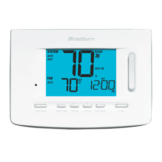
5050
USER MANUAL
Compatible with low voltage single stage gas,
oil or electric heating or cooling systems,
including single stage heat pumps. This
thermostat can also be used on 250mv to
750mv millivolt heating only systems. Do not
use this thermostat on applications with
voltages above 30 Volts AC.
READ ALL INSTRUCTIONS BEFORE PROCEEDING
CONTENTS
1
SPECIFICATIONS
2
INSTALLATION
3
TESTING YOUR NEW THERMOSTAT
PROGRAMMING
4
5
ADDITIONAL OPERATION FEATURES
TROUBLESHOOTING
6
7
WIRING DIAGRAMS
© 2005 Braeburn Systems LLC • Patents Pending • All Rights Reserved.
Premier Series
Universal 7 Day or 5-2
Day Programmable
Single Stage Heat/Cool
Digital Thermostat
Pub. No. 5050-100-006
WARNING!
Important Safety Information
• Always turn off power to the air conditioning or heating system prior to installing,
removing, cleaning or servicing thermostat.
• Read manual thoroughly prior to installing, programming or operating thermostat.
• This thermostat is designed for use with a 24 Volt-AC low voltage single stage
gas, oil or electric heating or cooling systems, including single stage heat
pumps. This thermostat can also be used on 250mv to 750mv millivolt heating
only systems.
• Do not use this thermostat on applications with voltages above 30 Volts AC.
• This thermostat requires two (2) properly installed "AA" alkaline batteries to
provide power for the thermostat to properly control the system operation.
• Wiring must conform to all building codes and ordinances as required by local and
national code authorities having jurisdiction.
• Do not short (or jumper) across terminals on the gas valve or at the heating or
cooling system control board to test the thermostat installation. This could
damage the thermostat and void the warranty.
• Do not select COOL mode of operation if the outside temperature is below 50˚ F
(10˚ C). This could damage the controlled cooling system and cause personal injury.
• This thermostat should only be used as described in this manual. Any other use is
not recommended and will void the warranty.
1 1
SPECIFICATIONS
• Electrical Rating: 24 Volt AC (18-30 Volt AC)
1 amp maximum load per terminal
2 amp total maximum load (all terminals)
• Control Range: 45˚ - 90˚ F (7˚ - 32˚ C)
• Accuracy: +/- 1˚ F (+/- .5˚ C)
• DC Power: 3.0 Volt DC (2 "AA" Alkaline batteries included)
• Compatibility: Compatible with low voltage single stage gas, oil or electric heating
or cooling systems, including single stage heat pumps. This thermostat can also
be used on 250mv to 750mv millivolt heating only systems.
• Terminations: Rc, Rh, G, W, Y, B, O
2
INSTALLATION
2.1
Replacing Existing Thermostat
1. Always turn off power to the air conditioning or heating system prior to removing
existing thermostat.
2. Remove the cover of your old thermostat and locate the wire terminals. Do not
remove wires from terminals yet.
3. Using small pieces of masking tape, label wires prior to removal from terminals. Use
the chart below to determine the new terminal designations for your new thermostat.
Old Terminal from
New Terminal for
Existing Thermostat
New Thermostat
V or Rc
Rc
M, 4, Rh, or R
Rh
G or F
G
H, W or 4
W
Y
Y
B
B
O
O
C
None (Cap the wire)
Terminal Description
Cooling Transformer
Heating Transformer
Fan Control
Heating Control
Cooling Control
Reversing Valve (Heating)
Reversing Valve (Cooling)
24 Volt AC, Transformer Common
1
Advertisement
Table of Contents

Related Manuals for Braeburn Premier 5050


Summary of Contents for Braeburn Premier 5050
-
Page 1: Installation
Fan Control H, W or 4 Heating Control Cooling Control Reversing Valve (Heating) Reversing Valve (Cooling) None (Cap the wire) 24 Volt AC, Transformer Common © 2005 Braeburn Systems LLC • Patents Pending • All Rights Reserved. Pub. No. 5050-100-006... -
Page 2: Testing Your New Thermostat
INSTALLATION INSTALLATION cont. cont. Replacing Existing Thermostat cont. Installing Your New Thermostat cont. 20. Using your finger, gently flip the switch towards the programing option which best 4. After labeling and removing all wires from terminals, unscrew the existing thermostat sub-base from wall. -
Page 3: Programming
PROGRAMMING PROGRAMMING cont. Setting the Temperature Differential Default Thermostat Settings Function Status After Reset The default setting is 0.5˚ F (0.25˚ C). The room temperature must change 0.5˚ F (0.25˚ C) from Operation Mode Normal Operating Mode the setpoint temperature before the thermostat will initiate the system in heating or cooling. Temperature Hold Extended and Temporary Hold Cleared 1. - Page 4 PROGRAMMING PROGRAMMING cont. cont. Programming Overview for 7 Day Programming Mode cont. Setting the Recirculating Fan Cycle (see also section 5.7) Whole Week – allows you to program all seven days (M, TU, W, TH, F, SA, SU will show in 12.
-
Page 5: Additional Operation Features
ADDITIONAL PROGRAMMING OPERATION FEATURES cont. Entering Your Program cont. Review Set Temperature 1. Press and hold button. The current setpoint temperature will be displayed in the 8. Place the system switch in the COOL mode of operation. The display will show COOL. Follow place of the current room temperature, and the indicator SET TEMP will be displayed. - Page 6 ADDITIONAL ADDITIONAL OPERATION FEATURES OPERATION FEATURES cont. cont. Adaptive Recovery Mode (ARM™) Compressor Protection In order to maximize comfort and energy efficiency, this thermostat is equipped with an This thermostat includes an automatic compressor protection feature to avoid potential Adaptive Recovery Mode (ARM™). This feature minimizes the amount of time required by damage to the cooling system from short cycling.
-
Page 7: Troubleshooting
TROUBLESHOOTING TROUBLESHOOTING cont. SYMPTOM POTENTIAL SOLUTION SYMPTOM POTENTIAL SOLUTION Thermostat does not Check to see if OFF is shown in display. This indicates that the Low battery indicator Replace batteries immediately to maintain proper system system is turned off at the thermostat. Move the system selector operation. -
Page 8: Wiring Diagrams
TROUBLESHOOTING WIRING DIAGRAMS cont. Typical 4-Wire Single Transformer Heating and Cooling System SYMPTOM POTENTIAL SOLUTION Thermostat will not This is above the normal thermostat temperature setting range Factory Installed of 45˚ to 90˚ F (7˚ to 32˚ C). allow me to program Jumper a setpoint temperature higher... - Page 9 Montgomery, IL 60538 Braeburn Systems LLC 2215 Cornell Avenue • Montgomery, IL 60538 Technical Assistance: www.braeburnonline.com Call us toll-free: 866-268-5599 (U.S. Only) 630-844-1968 (Outside the U.S.) © 2005 Braeburn Systems LLC • Patents Pending • All Rights Reserved. Pub. No. 5050-100-006...
Need help?
Do you have a question about the Premier 5050 and is the answer not in the manual?
Questions and answers