Braeburn PREMIER Series Installer's Manual
Non-programmable thermostats, up to 2 heat / 1 cool heat pump 1 heat / 1 cool conventional, up to 3 heat / 2 cool heat pump, up to 2 heat / 2 cool conventional
Hide thumbs
Also See for PREMIER Series:
- Installer's manual (20 pages) ,
- User manual (20 pages) ,
- Detailed installer manual (17 pages)
Table of Contents
Advertisement
Quick Links
Detailed
Installer Guide
Non-Programmable Thermostats
3020 Up to 2 Heat / 1 Cool Heat Pump
1 Heat / 1 Cool Conventional
3220 Up to 3 Heat / 2 Cool Heat Pump
Up to 2 Heat / 2 Cool Conventional
Model number is located on back of thermostat.
1 Specifications
4 Installer Settings
Warning
For installation by experienced service technicians only.
Caution
• Possible electric shock or damage to equipment can occur.
• Disconnect power before beginning installation.
This thermostat requires 24 Volt AC Power or 2 properly installed "AA" Alkaline
batteries for proper operation. When connecting 24 Volt AC Power the batteries may
be installed as a backup.
For use only as described in this manual. Any other use will void warranty.
1 Specifications
This thermostat is compatible with:
• Single stage heat / cool conventional and heat pump systems
• Single stage heat pumps with auxiliary heat
• Conventional systems up to 2 stages of heating and 2 stages of cooling (3220 only)
• Heat pump systems up to 3 stages of heating and 2 stages of cooling (3220 only)
• 250 – 750 millivolt heating only systems
• 2 or 3 wire hydronic zone systems
Electrical and control specifications:
• Electrical Rating: 24 Volt AC
• 1 amp maximum load per terminal
• AC Power: 18 – 30 Volts AC
• DC Power: 3.0 Volt DC (2 "AA" Alkaline Batteries Included)
• Control Range: 45° – 90° F (7° – 32° C)
• Temperature Accuracy: +/- 1° F (+/- .5° C)
• Outdoor Temperature Display Range: -40° - 120° F (-40° - 49° C)
Terminations
• 3020: G, Rc, Rh, W1/E, O/B/V3, Y1, C, S1, S2
• 3220: G, Rc, Rh, W1/E/W3, W2, O/B/V3, Y1, Y2, C, L, S1, S2
2 Installation and Wiring
®
3 Quick Reference
5 System Testing
P
REMIER
S
ERIES
3020W-100-03
Advertisement
Table of Contents

Subscribe to Our Youtube Channel
Related Manuals for Braeburn PREMIER Series


Summary of Contents for Braeburn PREMIER Series
- Page 1 ® Detailed REMIER ERIES Installer Guide Non-Programmable Thermostats 3020 Up to 2 Heat / 1 Cool Heat Pump 1 Heat / 1 Cool Conventional 3220 Up to 3 Heat / 2 Cool Heat Pump Up to 2 Heat / 2 Cool Conventional Model number is located on back of thermostat.
-
Page 2: Installation And Wiring
Avoid installation in locations where the thermostat can be affected by drafts, dead air spots, hot or cold air ducts, sunlight, appliances, concealed pipes, chimneys and outside walls. Install your new Braeburn thermostat in 4 basic steps: 1 Install the Sub-Base... - Page 3 Provide Power 24VAC Power Terminal (C) Batteries Installed as Shown • For 24 Volt AC power, you must connect the common side of the transformer to the C terminal on the thermostat sub-base. In dual transformer installations, the transformer common must come from the cooling transformer. •...
-
Page 4: Function Description
Connecting Your Wires (continued) Wiring Terminations for model 3220 Terminal Function Description Input 24 Volt AC Cooling Transformer (Dual Transformer Systems Only) Input Power Connection (24 Volt AC Heating Transformer or Millivolt Power Source) Output Fan Control W1 / E / W3 Output (W1) 1st Stage Conventional Heat, (E) Emergency Heat,... -
Page 5: Conventional Systems
NOTES - Additional Wiring Options NOTE: Additional options are configured in the Installer Settings section. [1] These terminals can be used to connect a Braeburn indoor or outdoor remote sensor. ® Indoor or Outdoor Remote Sensor [note 1] Installer Guide... -
Page 6: Heat Pump Systems
NOTE: Additional options are configured in the NOTES - Additional Wiring Options Installer Settings section. [1] These terminals can be used to connect a Braeburn indoor or outdoor remote sensor. ® Indoor or Outdoor Remote Sensor [note 1] Installer Guide... -
Page 7: Attach Thermostat To Sub-Base
Attach Thermostat to Sub-Base INSTRUCTIONS 1) Line up the thermostat body with the sub-base. 3) Insert Quick Reference Card into slot 2) Carefully push the thermostat body against the on top of thermostat. sub-base until it snaps in place. NOTE: This thermostat ships configured as a 1H/1C conventional thermostat. -
Page 8: Quick Reference
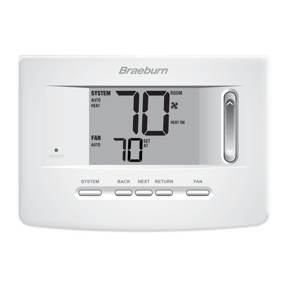
® Outdoor Temperature Indicator..Displays along with the outdoor temperature reading (see note below) Battery Compartment ....Located in the back of thermostat NOTE: If a Braeburn outdoor sensor was connected you can view the outdoor temperature by ® pressing the BACK and NEXT buttons at the same time. -
Page 9: Installer Settings
4 Installer Settings The Installer Settings must be properly configured in order for this thermostat to operate correctly. The Installer Settings are menu driven. The portion of these settings that do not apply to your setup will be skipped. These settings are indicated below with comments. - Page 10 ® 8 Only available if auto changeover was enabled in option 2. 9 Only available if a Braeburn outdoor sensor was connected. Detailed Explanation of Installer Settings (also see NOTES above): Temperature Scale – Selects a temperature scale of either °F or °C.
- Page 11 (I SENS), remote sensor only (E SENS) or combining the thermostat and the remote sensor (A SENS). NOTE: This option does not apply to a Braeburn outdoor sensor. When an outdoor sensor is connected the thermostat automatically recognizes it and no further configuration is necessary.
-
Page 12: System Testing
21 Heat Set Point Upper Limit – Selects the heating set point upper adjustment limit. 22 Cool Set Point Lower Limit [note 6] – Selects the cooling set point lower adjustment limit. 5 System Testing Warning Read Before Testing • Do not short (or jumper) across terminals on the gas valve or at the heating or cooling system control board to test the thermostat installation. -
Page 13: Limited Warranty
Montgomery, IL 60538 Store this manual for future reference. ® Braeburn Systems LLC 2215 Cornell Avenue • Montgomery, IL 60538 Technical Assistance: www.braeburnonline.com Call us toll-free: 866-268-5599 (U.S.) 630-844-1968 (Outside the U.S.) 3020W-100-03 ©2020 Braeburn Systems LLC • All Rights Reserved.
Need help?
Do you have a question about the PREMIER Series and is the answer not in the manual?
Questions and answers