Braeburn PREMIER Series Installer's Manual
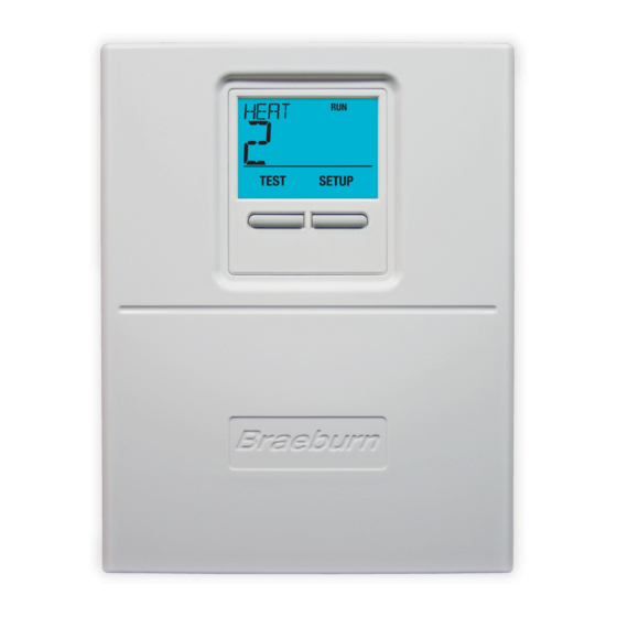
2 zone expander panel
Hide thumbs
Also See for PREMIER Series:
- Installer's manual (20 pages) ,
- User manual (20 pages) ,
- Detailed installer manual (17 pages)
Advertisement
Quick Links
140424
2 Zone
Expander Panel
For Use with Braeburn
Model 140404
Store this manual for future reference.
Warning
Caution
Can cause electrical shock or equipment damage. Always turn off power to the heating/air
conditioning system prior to installing or adjusting the Zone Panel Expander. Complete the
wiring for the main panel and expansion panel before applying transformer power.
This panel is designed for professional installation, and is to be installed and configured as
described in this manual. Any other use is not recommended and will void the warranty.
Install disconnect and overload protection on circuits as required by code authorities having
jurisdiction for the installation.
P
S
REMIER
ERIES
Read all of the instructions before proceeding
Voltage Hazard
®
Installer Guide
140424-100-03
Advertisement

Related Manuals for Braeburn PREMIER Series


Summary of Contents for Braeburn PREMIER Series
- Page 1 ® 140424 Installer Guide 2 Zone Expander Panel For Use with Braeburn Model 140404 Store this manual for future reference. Warning Read all of the instructions before proceeding Caution Voltage Hazard Can cause electrical shock or equipment damage. Always turn off power to the heating/air conditioning system prior to installing or adjusting the Zone Panel Expander.
-
Page 2: Table Of Contents
Table of Contents 1 Specifications........................2 2 Suitable Mounting Locations....................3 3 Wiring Diagrams......................5-9 4 Zone Addressing.........................9 5 Adding Zones to Main Panel....................10 6 Operation..........................10 7 Error Conditions........................ 11 8 Warranty........................... 1 2 Figure 1 Specifications Protection: Storage temperature: -40˚–167˚F (-40˚–75˚C) Electronic self resetting current 5.1”... -
Page 3: Suitable Mounting Locations
Suitable Mounting Locations Mount the Zone Panel Expander near the Main Panel. If desired, the expander panel can be mounted up to 500 feet from the main panel. The panel can be mounted in any orientation on a wall, stud, roof truss, or the return-air plenum. - Page 4 Wiring the Panel Always turn off power to the heating/air conditioning system prior to installing or adjusting the Zone Panel Expander. Use the following general wiring instructions for all systems. Specific wiring will vary depending on the type of thermostats and dampers used for the installation. NOTE: Up to 2 wires can be inserted into each terminal position.
-
Page 5: Wiring Diagrams
ZONE PANEL EXPANDER WIRING TERMINALS Terminal Qty. Function Description PANEL INPUT 24 VAC Transformer Power 75 VA Maximum POWER INPUT 24 VAC Transformer Common DAMPERS OUTPUT 24 VAC Power Open Zone Damper Terminal OUTPUT Zone Damper Common Terminal OUTPUT 24 VAC Power Close Zone Damper Terminal EXPANSION COM1 OUTPUT... - Page 6 Example Wiring Options Daisy Chain All Zones Star Wiring All Zones Located at Main Panel Located at Main Panel Expander Panel Expander Panel As Needed Zones 7-8 Main Panel Main Panel Expander Panel Zones 5-6 Expander Panel Expander Panel Expander Panel As Needed Zones 5-6 Zones 7-8...
- Page 7 Damper Wiring Install the system dampers using the instructions provided by the manufacturer. Connect the dampers to the zone panel expander as shown for either a 2-wire Zone Panel 2-Wire Damper or 3-wire damper. The sum of all dampers powered by the zone panel should not exceed 75 VA at 24 VAC.
- Page 8 HEAT PUMP THERMOSTATS 3 HEAT / 2 COOL - With Auxiliary Heat 24 VAC Power 1 HEAT / 1 COOL - No Auxiliary Heat Changeover Valve [Note 2] 24 VAC Power Optional System Fault Monitor O/B Changeover Valve [Note 2] Auxiliary Heat Relay (3rd Stage Heating) Compressor Call (1st Stage Heating/Cooling) Compressor Call (1st Stage Heating/Cooling)
-
Page 9: Zone Addressing
Transformer Wiring Install the transformer using the instructions provided by the manufacturer. Size the transformer to the damper requirements. The zone panel has a built-in, self- resetting fuse. The maximum damper power per zone is 75 VA at 24 VAC. Connect the transformer to the zone panel as shown. -
Page 10: Adding Zones To Main Panel
Add Zones to Main Panel The 4 Zone Expandable Panel can be expanded to up to 32 zones with four zones on the main panel and 28 total expansion zones. Additional zones must have power and communication wires to be recognized and controlled by the main expandable panel. -
Page 11: Error Conditions
Error Conditions The Main Panel continually monitors various components of the zone system and will display a message when the following Expander Panel monitored conditions are detected. Invalid Address on Expansion Panel Displayed when an invalid address has been set on an expansion panel. -
Page 12: Warranty
Store this manual for future reference. ® Braeburn Systems LLC 2215 Cornell Avenue • Montgomery, IL 60538 Technical Assistance: www.braeburnonline.com Call us toll-free: 866-268-5599 (U.S.) 630-844-1968 (Outside the U.S.) 140424-100-03 ©2019 Braeburn Systems LLC • All Rights Reserved • Made in China.
Need help?
Do you have a question about the PREMIER Series and is the answer not in the manual?
Questions and answers