Advertisement
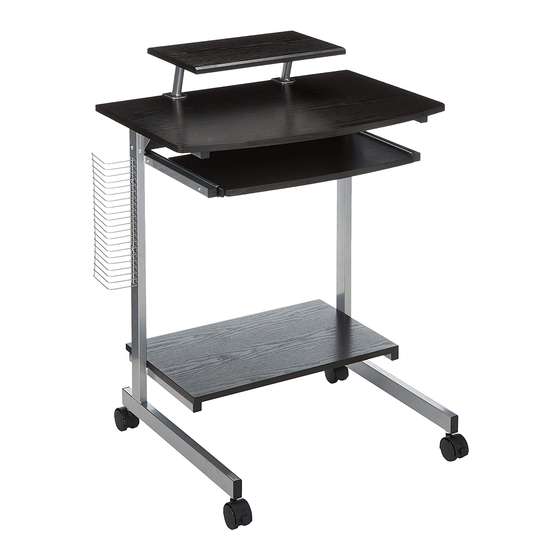
MODEL RTA-2018
ASSEMBLY INSTRUCTIONS
☛
Assembly video also available online at technimobili.com
Thank you for purchasing one of our products.
Please read carefully the assembly instructions before the installation.
Do not discard this manual or any of the packaging material until the unit has
.
been completely assembled
With adjustable shelf
By
Advertisement
Table of Contents

Related Manuals for RTA Techni Mobili RTA-2018


Summary of Contents for RTA Techni Mobili RTA-2018
- Page 1 MODEL RTA-2018 ASSEMBLY INSTRUCTIONS ☛ Assembly video also available online at technimobili.com Thank you for purchasing one of our products. Please read carefully the assembly instructions before the installation. Do not discard this manual or any of the packaging material until the unit has...
- Page 2 RTA-2018 MAIN PARTS LIST ❷ ❶ ❶ Locking Caster ❷ Non- Locking Caster Right structure Left structure ❸ ❹ Lower panel Back panel ❺ ❻ ❼ Main panel Keyboard slider SET Keyboard panel �� ❿ ⓫ ❽ Printer/Monitor panel ❾...
- Page 3 RTA-2018 SCREWS LIST SIZE / PART FIGURE DESCRIPTION �� 6x45mm �� 6x30mm �� 6x12mm �� 4x12mm Hex Wrench Allen Wrench Hex/Phillips BEFORE YOU START THE ASSEMBLY, PLEASE READ THE FOLLOWING TIPS AND WARNINGS. • Do a quick inventory to make sure the product contains all the parts and hardware.
- Page 4 RTA-2018 ASSEMBLY STEPS STEP 1 Using the wrench, assemble the casters ② to the structures ①L, ①R in the following order: ☛ The locking casters ②L go on the front bottom holes, ☛ The non-locking casters ②N go on the back bottom holes.
- Page 5 RTA-2018 Use screws Ⓑ to assemble the lower panel ④ to the lower bars on the structures ①L, STEP 3 ①R from underneath as shown. Screws: 6x30mm Ⓑ STEP 4 Use screws Ⓑ to assemble the main panel ⑤ to the top bars of the structures ①L and ①R from underneath as shown.
- Page 6 RTA-2018 Use screws Ⓓ to assemble the keyboard panel ⑦ to the sliders ⑥ from underneath as STEP 6 shown. Screws: 4x12mm Ⓓ STEP 7 Use screws Ⓒ to assemble the CD rack ⑨ to either structure ①L or ①R according tp your preference.
- Page 7 RTA-2018 Assemble the support tubes ⑩A to the main panel ⑤ in the position of your preference STEP 9 making sure that the protection clips ⑩B are positioned in between, then use the screw knobs ⑩C to secure the tubes as shown.
- Page 8 RTA-2018 AFTER THE ASSEMBLY IS DONE, PLEASE READ CAREFULLY THE FOLLOWING CARE AND MAINTENANCE WARNINGS: 30 Lbs. (13.60 Kg) WEIGHT LIMITS 100 Lbs. (45.36 Kg) 22 Lbs. (9.97 Kg) 30 Lbs. (13.60 Kg) • Do not exceed the indicated weight limits.
Need help?
Do you have a question about the Techni Mobili RTA-2018 and is the answer not in the manual?
Questions and answers